Sign In
Upload
Manuals
Brands
Siemens Manuals
Controller
Synco RMK770
Siemens Synco RMK770 Manuals
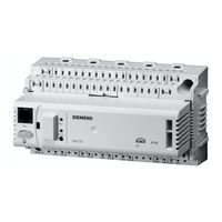
Manuals and User Guides for Siemens Synco RMK770. We have
6
Siemens Synco RMK770 manuals available for free PDF download: Basic Documentation, Operating Instructions Manual, Installation Instructions Manual
Siemens Synco RMK770 Basic Documentation (232 pages)
Modular boiler sequence controller including extension modules RMZ785, RMZ787, RMZ788 and RMZ789
Brand:
Siemens
| Category:
Controller
| Size: 2.58 MB
Table of Contents
Table of Contents
3
1 Summary
11
Product Range
11
System Topology
12
Equipment Combinations
12
Product Documentation
13
Important Notes
14
2 Operation
15
Operation Without Operator Unit
15
Operation with Operator Unit
16
Functions of the Operator Unit
16
Operating Concept
16
Operating Levels
17
Access Rights
18
3 Commissioning
19
Basic Concept
19
Entering the Commissioning Mode
22
Basic Configuration
22
Plant Types
22
Terminal Assignment and Properties of Outputs
31
Short Designations for Basic Module and Extension Modules
32
Maximum Configuration
32
Use of Configuration Diagrams
32
Extension Modules
34
Extra Configuration
36
Hydraulics-Dependent Inputs and Outputs of Function Block "Boiler Sequence Manager
37
Hydraulics-Dependent Inputs and Outputs of Function Block "Boiler
38
Hydraulics-Dependent Inputs and Outputs of Function Block "Precontrol
39
Hydraulics-Dependent Inputs and Outputs of Function Block "Heating Circuit
40
Miscellaneous
41
Faults
42
Configuration of the Universal Inputs and Outputs
42
Several Boiler Sequence Controllers RMK770
44
Wiring Test
45
Completing Commissioning
46
Data Backup
46
Device Information
46
Leaving the Password Level
47
Marking Changes
47
Plant Types and Default Terminal Assignments
48
4 General Settings
52
Time of Day and Date
52
Operating Principle
52
Communication
52
Fault Handling
53
Selecting the Language
54
Selecting the Unit of Temperature
54
Contrast of the Operator Unit's Display
54
Text Entry
54
Device Name and File Name
54
Aggregate Names
55
Text of Fault Inputs
55
Electronic Business Card
55
Resetting Text Entries
56
5 General Functions, Fundamentals
57
Time Switch
57
Communication
57
Entering the 24-Hour Program for Space Heating
58
Fault Handling
59
Holidays / Special Days
59
Communication
59
Holidays
60
Special Days
60
Calendar Entry
61
Control Inputs for Holidays and Special Days
61
Fault Handling
62
Frost Protection for the Plant
62
Pump Overrun and Mixing Valve Overrun
63
Pump Kick and Valve Kick
63
Heat Demand and Load Control
64
Heat Demand
64
Load Control
65
Mixing Valve Control
66
Control
66
Setting Aids
67
Control Signal
69
Pump Control
69
Hours Run Counter
69
Pump Supervision and Twin Pumps
70
Changeover Logic
71
Overload Message and Supervision of Flow
72
6 Boiler Sequence Management
73
Overview of Function Block
73
Configuration
74
Boiler Sequence Management
77
Concept
77
Orders for Boilers to be Switched on and off
78
Boiler Sequence Order
81
Boiler Sequence Operating Mode
83
Sustained Mode
85
Switching Boilers on and off
85
Supervision of Faults
89
Heat Demand and Heat Request
91
Heat Request Modulating
92
Heat Request 2-Position
92
Heat Demand Transformers
93
Other Functions
93
Common Maintained Boiler Return Temperature
93
Maximum Limitation of the Flow Temperature Setpoint
94
Frost Protection
95
Diagnostics
95
Fault Handling
97
7 Boiler Control
99
Overview of Function Block
99
Configuration
101
Burner Types
103
Boiler Hydraulics
104
Additional Boilers
106
Boiler Operating Modes and Boiler Setpoints
106
Releasing and Locking a Boiler
106
Individual Operation
107
Test Mode and Commissioning Aids
108
Control of the Burner
109
2-Position Control of 1-Stage Burners
109
2-Position Control of 2-Stage Burners
110
Control of Burner's Basic Stage and Stage 2
110
Control of Modulating Burners
112
External Burner Control
116
Protective Boiler Functions
116
Maximum Limitation of the Boiler Temperature
117
Minimum Limitation of the Boiler Temperature
117
Protective Boiler Startup
117
Optimization of the Minimum Boiler Temperature
118
Boiler Shutdown
118
Protection against Boiler Overtemperatures
119
Pump Kick and Valve Kick
119
Frost Protection for the Plant with Boiler Pump
119
Frost Protection for the Boiler
119
Protection against Pressure Shocks
120
Minimum Limitation of the Return Temperature
120
Flue Gas Temperature Supervision
122
Flue Gas Measuring Mode
123
Boiler Faults
124
Burner Hours Run Counter and Output Balance
126
Fault Status Messages
127
Boiler Designations
132
Diagnostic Choices
132
8 Heat Demand and Heat Requests
134
Heat Requests
134
Weather-Compensated Setpoint for Boiler Sequencing
135
Heat Demand Transformers
135
9 Precontrol
138
Overview of Function Block
138
Configuration
138
Types of Primary Controller
139
Control of Mixing Valve
139
Pump Control
139
Plant Operation
140
Heat Demand and Heat Request
140
Heat Request Modulating
141
Heat Request 2-Position
142
Heat Demand Transformers
142
Control of Mixing Valve
143
General
143
Load Control
143
Setpoint Boost Mixing Valve and System Pump
143
Limit and Protective Functions
144
Frost Protection
144
Limitations
144
Limitation of the Return Temperature
145
Pulse Limitation
146
Pump Overrun and Mixing Valve Overrun
147
Pump Kick and Valve Kick
147
Text Designation
147
Fault Handling
148
Diagnostic Choices
148
10 Heating Circuit Control
150
Overview of Function Block
150
Configuration
150
3-Position or Modulating Mixing Valve
152
Pump Control
152
Heating Circuit Operating Mode
152
Room Operating Modes
152
User Requests from the Room
154
Room Operating Mode Contact
154
Timer Function
155
Room Operating Mode Outputs
155
Plant Operation
157
Control Priorities in the Heating Circuit
157
Room Temperature Setpoints
159
Settings
159
Increasing the Economy Setpoint
160
Room Temperature Setpoint Adjuster, Absolute
160
Room Temperature Setpoint Adjuster, Relative
162
Weather-Compensated Heating Circuit Control
162
The Composite and the Attenuated Outside Temperature
163
Heating Curve
164
Influence on the Flow Temperature Setpoint
166
Heating Limit Switch
167
Mixing Valve Control
168
Control
168
Load Control
169
Optimization Functions
170
Type of Optimization
170
Otimum Start / Stop Control
171
Quick Setback and Boost Heating
171
Limit and Protective Functions
172
Maximum Limitation of the Room Temperature
172
Return Temperature Limitation
173
Pulse Limitation
175
Frost Functions and General Protective Functions
175
Pump Overrun and Mixing Valve Overrun
176
Pump Kick and Valve Kick
176
Heat Demand
176
Extra Functions
177
Text Designations
177
Acquisition of the Room Temperature
177
Room Control Combination
179
Fault Handling
181
Diagnostic Choices
182
11 Data Acquisition
184
Trend
184
Connections and Use
184
Views
184
Trend Function Settings
185
Fault Handling
186
Meters
186
Configuration
186
Meter Types
186
Pulse Valency
187
Overflow Value
188
Setting and Resetting Meter Readings
188
Meter Readings
188
Assignment of Texts
189
Fault Handling
189
12 Function Block "Miscellaneous
190
Overview of Function Block
190
Configuration
190
Outside Sensor
190
Outside Temperature Simulation
192
Fault Handling
192
Display Inputs
193
Outside Temperature Relay
194
Diagnostic Choices
194
13 Function Block "Faults
195
Overview of Function Block
195
Configuration
195
Fault Button
195
External Fault Button
196
Fault Properties
196
Acknowledgement and Reset
196
Signal Priority
197
Plant Behavior
197
State Diagrams of the Individual Types of Fault
198
Predefined Fault Inputs
199
Fault Inputs
199
Universal Fault Inputs
199
Analog Fault Input with Limit Value Supervision
201
Communication
202
Fault Relays
202
Display of Faults
204
Deletion of All Fault Status Messages
204
Function Check and Wiring Test
204
Diagnostic Choices
205
14 Communication
206
Basic Settings
206
Calendar Data (Holidays and Special Days)
207
Room Data
208
Communication Variants
208
Settings
208
Settings on the Room Unit
209
Heat Generation Zone and Boiler Sequence Zone
209
Heat Distribution Zones
210
Heat Demand and Load Control
211
Outside Temperature
211
Fault Handling
212
15 Fault Tracing Support
214
Fault Code List
214
Rectification of Faults
217
16 Addendum
218
Configuration Diagrams
218
Terminal Markings
218
Code Letters
218
Configuration Choices
218
Configuration Diagram Plant Type K
219
Configuration Diagram Plant Type K1.1
220
Editable Texts
221
Boiler Sequence Manager
221
Boilers
221
Primary Controller
222
Heating Circuit
222
Faults
223
Meters
223
Devices
223
Menu Tree
223
Info
224
Advertisement
Siemens Synco RMK770 Operating Instructions Manual (138 pages)
Heating Controller; Boiler Sequence Controller
Brand:
Siemens
| Category:
Controller
| Size: 0.76 MB
Table of Contents
Deutsch
4
Table of Contents
4
Die Bedienelemente
5
Das Anzeigefeld
6
Die Symbole und Zeichen in der Anzeige
7
Die Navigation IM Menü
8
Wollen Sie jetzt mit dem Heizen Ihrer Räume Beginnen
10
Wollen Sie nach Heizprogramm Heizen
11
Wollen Sie die Täglichen Heizphasen Ändern
12
Wollen Sie nicht nach Heizprogramm Heizen
14
Welche Raumtemperatur können Sie Einstellen
15
Ist die Raumtemperatur zu Hoch oder zu Tief
16
Wollen Sie den Aktuellen Anlagenzustand des Heizkreises Abfragen
17
Wollen Sie den Brauchwasserbetrieb Starten
18
Ist das Brauchwasser zu Warm oder zu Kalt
19
Wollen Sie das Brauchwasser-Zeitprogramm Ändern
20
Müssen Sie die Zeit oder das Datum Neu Einstellen
21
Wollen Sie Ferienperioden Eingeben
22
Wollen Sie Sondertage Eingeben
23
Wollen Sie Aktuelle Anlagendaten Abfragen
24
Steht eine Störung an
25
Können diese Tipps bei Problemen Weiterhelfen
26
Wie Spart man Energie ohne Komforteinbusse
27
Infoseite Kesselfolge
28
Infoseiten Kesselfolgemanager
29
Infoseiten Kessel / Vorregler / Hauptregler
30
Diverse Infoseiten
31
Hauptmenü Kesselfolgemanager
32
Hauptmenü Kessel (1
33
Hauptmenü Vorregler / Hauptregler
34
Abgasmessbetrieb
35
English
38
The Operating Elements
39
The Display
40
The Symbols Appearing on the Display
41
Navigating through the Menu
42
Do You Want to Start Heating Your Rooms Now
44
Do You Want to Heat According to the Heating Program
45
Do You Want to Change the Daily Heating Periods
46
You Don't Want to Heat According to the Heating Program
48
What Room Temperature Can You Set
49
Is the Room Temperature too High or too Low
50
Do You Want to Display the Current Operating State of the Heating Circuit
51
Do You Want to Start DHW Heating
52
Is the DHW too Hot or too Cold
53
Do You Want to Change the DHW Time Program
54
Do You Want to Readjust the Time of Day or the Date
55
Do You Want to Enter Holiday Periods
56
Do You Want to Enter Special Days
57
Do You Want to Have Current Plant Data Displayed
58
A Fault Has Occurred
59
Saving Energy Without Sacrificing Comfort
61
Info Page Boiler Sequence
62
Info Pages Boiler Sequence Manager
63
Info Pages Boiler / Primary Controller / Main Controller28
64
Other Info Pages
65
Main Menu Boiler Sequence Manager
66
Main Menu Boilers (1
67
Main Menu Primary Controller / Main Controller
68
Flue Gas Measuring Mode
69
Français
72
Eléments de Commande
73
Ecran D'affichage
74
Symboles Utilisés Dans L'affichage
75
Navigation Dans Le Menu
76
Souhaitez-Vous Chauffer Vos Pièces Maintenant
78
Souhaitez-Vous Chauffer Selon Le Programme de Chauffage
79
Souhaitez-Vous Modifier Le Programme de Chauffage Journalier
80
Vous Ne Souhaitez Pas Chauffer Selon Le Programme de Chauffage
82
Quelle Température Ambiante Souhaitez-Vous Régler
83
La Température Ambiante Est Trop Élevée Ou Trop Basse
84
Souhaitez-Vous Connaître L'état Actuel de L'installation
85
Souhaitez-Vous Activer Le Régime ECS
86
L'eau Sanitaire Est Trop Chaude Ou Trop Froide
87
Souhaitez-Vous Modifier Le Programme Horaire D'ecs
88
Souhaitez-Vous Changer L'heure Ou la Date
89
Souhaitez-Vous Programmer Les Périodes de Vacances
90
Souhaitez-Vous Programmer des Jours D'exception
91
Souhaitez-Vous Consulter Les Données Actuelles de L'installation
92
Un Dérangement S'est Produit
93
Les Conseils Suivants Vous Aident-Ils À Résoudre Le Problème
94
Economies D'énergie Et Confort
95
Page Info Séquence de la Chaudière
96
Pages D'infos Pilote Cascade Chaudières
97
Pages D'infos Chaudière / Prérégulateur / Régulateur Principal
98
Pages D'infos Diverses
99
Menu Principal Pilote Cascade Chaudières
100
Menu Principal Chaudière (1
101
Menu Principal Prérégulateur / Régulateur Principal
102
Mode de Mesure des Fumées
103
Dutch
106
De Bedieningselementen
107
De Display
108
De Symbolen en Tekens in de Display
109
Navigatie Door Het Menu
110
Wilt U Nu Met Verwarmen Beginnen
112
Wilt U Volgens Het Verwarmingsprogramma Verwarmen
113
Wilt U de Dagelijkse Verwarmingsperioden Wijzigen
114
Wilt U Niet Volgens Het Verwarmingsprogramma Verwarmen
116
Welke Ruimtetemperatuur Kunt U Instellen
117
Is de Ruimtetemperatuur te Hoog of te Laag
118
Wilt U Informatie over de Toestand Van de Installatie
119
Wilt U de Tapwatervoorziening Starten
120
Is Het Tapwater te Warm of te Koud
121
Wilt U Het Tijdprogramma Voor Het Tapwater Wijzigen
122
Moet U de Tijd of de Datum Opnieuw Instellen
123
Wilt U Vakantieperioden Invoeren
124
Wilt U Bijzondere Dagen Invoeren
125
Wilt U Actuele Installatiegegevens Opvragen
126
Is er Een Storing Aanwezig
127
Tips Bij Problemen
128
Hoe Bespaart U Energie Zonder Comfortbeperkingen
129
Infoblad Ketelvolgorde
130
Infobladen Ketelvolgorderegelaar
131
Infobladen Ketel / Voorregeling / Hoofdregelaar
132
Diverse Infobladen
133
Hoofdmenu Ketelvolgorderegelaar
134
Hoofdmenu Ketel (1
135
Hoofdmenu Voorregeling / Hoofdregelaar
136
Rookgas Meetbedrijf
137
Siemens Synco RMK770 Basic Documentation (120 pages)
Communication via the KNX bus
Brand:
Siemens
| Category:
Controller
| Size: 1.98 MB
Table of Contents
Table of Contents
3
1 KNX (Konnex) and Synco
7
General Overview
7
Definition of Terms
8
Synco 700, 900, RXB/RXL Range
10
Collective Terms for the Device Types
11
Product Markings on Synco Bus Devices
11
The KNX Network
12
Full-Scale KNX Network
12
Network Address
13
Device Address
14
Area/Line Couplers and IP Router
15
2 Engineering Notes
17
Designing the Network
17
Design Engineering Procedure
17
Number of Bus Devices Per Line, Area and Network
18
Bus Load Number E
18
Bus Power Supply
19
Decentral Bus Power Supply
19
Power Consumption of the Bus Devices
20
Central Bus Power Supply
21
Bus Topologies
22
Distances and Cable Lengths
23
3 Commissioning Notes
25
Points to Check Prior to Commissioning
25
Commissioning with the RMZ Operator Units
26
Starting Commissioning, Plant Mode "Off
26
Terminating Commissioning, Plant Mode "Auto
28
4 Device Address and Device Name
29
Reading the Area, Line and Device Address
29
Assigning Device Names
30
Setting Device Address with RMZ790 and RMZ791 Operator Units
32
5 Device Addresses Via ACS
33
Service Tool OCI700.1 and ACS7
33
Overview
33
New Plant
34
Establishing a Connection
35
Edit Device List
35
Addressing Devices with the OCI700.1 Service Tool
37
Assigning Addresses Manually
38
Assigning Addresses Automatically
39
Assigning Addresses in Programming Mode
40
Addressing Via the ID Number
41
Device Address for the Ozw771.XX Central Communication Units
42
Other Addressing Options, Ozw771.XX
43
Restoring the Factory Settings, Ozw771.XX
43
Device Address for the OZW775 Central Communication Unit
44
Device Address for the QAX910 Central Apartment Unit
45
Device Address for the RXB/RXL Room Controllers
48
RXB/RXL Device Address with QAX34.3 Room Unit
49
Device Address for the QAW740 Room Unit
51
Device Address for RMZ792 Bus Operator Unit
53
Addressing the Couplers
56
Line Couplers
56
Area Couplers
58
5.10 Addressing the IP Router
59
5.10.1 KNX Network Address
59
6 Basic Communication Settings
61
Decentral Bus Power
61
Clock Time Operation
61
Setting a Time Slave Remotely
62
Remote Reset of Fault
64
Basic Settings Via ACS
65
7 Communication Via Zone Addresses
67
General Notes on Zones
67
Synco Zoning
67
Communication of Process Values
68
Geographical Zone (Apartment)
69
Default
70
Zone Addressing with the RMZ Operator Units
72
QAWZ740 Room Unit
73
Addressing the Zones with ACS
74
RXB/RXL Room Controllers
75
Zone Addressing with the QAX34.3 Room Unit
75
8 Large Plants
77
Engineering and Commissioning
77
Network Topologies
78
IP Router as a Coupler to the IP Network
81
LTE Filter Table for Couplers and IP Routers
84
Filter Settings
84
Predefined LTE Filter Table
85
Filtering, Zone Addresses, Communication Areas
86
LTE Telegrams Via Couplers and IP Routers
87
System Time, Alarms and Remote Time Adjustments
89
Engineering of Large Plants
90
9 Appendix
93
Faults and Errors
93
Bus Fault Status Message
93
Communication Errors
94
Heating / Cooling Changeover
95
Changeover Via Digital Input
96
Changeover Via Analog Input
97
Changeover Based on Calendar
98
H/C Changeover Relay and Fault Messages
99
Room Control Combination
100
Application Examples
100
Applications with Zones
104
Additional Zones in the RXB/RXL Room Controller
105
Supply Chains
106
Data Exchange in LTE Mode
108
Updating the Process Values
109
Lightning and Overvoltage Protection, EMC
110
Lightning Protection
110
Overvoltage Protection
113
Overvoltages in Loops
114
EMC Protection Management
115
Advertisement
Siemens Synco RMK770 Basic Documentation (88 pages)
KNX bus communications
Brand:
Siemens
| Category:
Home Automation
| Size: 0.96 MB
Table of Contents
Table of Contents
3
1 KNX and Synco
5
General Overview
5
Definition of Terms
6
Device Range
8
Collective Terms for the Device Types
9
Product Markings on Synco Bus Devices
10
The KNX Network
11
Full-Scale KNX Network
11
Network Address
12
Device Address
13
Area/Line Couplers and IP Router
14
2 Engineering Notes
15
Network Design
15
Design Engineering Procedure
15
Number of Bus Devices Per Line, Area and Network
16
Bus Load Number E
17
Bus Power Supply
17
Distributed Bus Power
17
Power Consumption of Bus Devices
19
Central Bus Power Supply
20
Bus Topologies
21
Distances and Cable Lengths
22
3 Commissioning Notes
25
Points to Check Prior to Commissioning
25
Commissioning with RMZ Operator Units
26
Start Commissioning, Plant Mode "Off
26
Finish Commissioning, Plant Mode "Auto
28
4 Device Address and Device Name
29
Read Area, Line and Device Address
29
Assign Device Names
30
Set Device Address with RMZ790 and RMZ791 Operator Units
32
5 Device Addresses Via ACS
33
Service Tool OCI700.1 and ACS790 Software
33
Overview
33
6 Basic Communication Settings
35
Distributed Bus Power
35
Clock Time Operation
35
Set Time Slave Remotely
36
Remote Reset of Fault
38
7 Communication Via Zone Addresses
39
General Notes on Zones
39
Synco Zoning
39
Communication of Process Values
40
Geographical Zone (Apartment)
41
Default Value
42
LTE Reception and Transmission Zones
44
Address Zones with RMZ Operator Units
46
QAW740 Room Unit
46
8 Large Plants
47
Engineering and Commissioning
47
Network Topologies
48
IP Router as Coupler to IP Network
51
LTE Filter Table for Couplers and IP Routers
54
Filter Settings
54
Predefined LTE Filter Table
55
Filtering, Zone Addresses, Communication Areas
56
LTE Telegrams Via Couplers and IP Routers
57
System Time, Alarms, and Remote Time Adjustment
59
Engineering Large Plants
60
9 Appendix
63
Faults and Errors
63
Fault Status Message Bus
63
Communication Error
64
Heating/Cooling Changeover
65
Changeover Via Digital Input
66
Changeover Via Analog Input
67
Changeover Based on Calendar
68
H/C Changeover Relay and Fault Status Messages
69
Room Control Combination Function
70
Application Examples
70
Application with Zones
74
Additional Zones in the RXB/RXL Room Controller
75
Supply Chains
76
Data Exchange in LTE-Mode
78
Update Process Values
79
Lightning and Overvoltage Protection, EMC
80
Lightning Protection
80
Overvoltage Protection
83
Overvoltages in Loops
84
EMC Protection Management
85
Index
86
Siemens Synco RMK770 Installation Instructions Manual (19 pages)
Brand:
Siemens
| Category:
Control Unit
| Size: 0.97 MB
Table of Contents
First Start-Up
3
Mise en Service
4
Messa in Servizio
5
Ensimmäinen Käynnistys
6
Puesta en Marcha
6
UváDění Do Provozu
8
Uvedenie Do Prevádzky
9
Üzembe Helyezés
9
Punere in Functiune
12
Siemens Synco RMK770 Installation Instructions Manual (20 pages)
Brand:
Siemens
| Category:
Control Unit
| Size: 1.12 MB
Table of Contents
Messa in Servizio
5
Puesta en Marcha
6
UváDění Do Provozu
8
Uvedenie Do Prevádzky
9
Punere in Functiune
12
Advertisement
Related Products
Siemens RMH760
Siemens RMU7*B series
Siemens RMS705
Siemens Synco RMU710
Siemens Synco RMU720
Siemens Synco RMU730
Siemens RMU7 Sereis
Siemens RMB795 RMS705
Siemens RMU7 B Series
Siemens RMU730B-1
Siemens Categories
Industrial Equipment
Controller
Control Unit
Oven
Washer
More Siemens Manuals
Login
Sign In
OR
Sign in with Facebook
Sign in with Google
Upload manual
Upload from disk
Upload from URL