Sign In
Upload
Manuals
Brands
Toshiba Manuals
Heat Pump
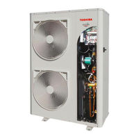
Estia RUA-CP2101H
Toshiba Estia RUA-CP2101H Manuals
Manuals and User Guides for Toshiba Estia RUA-CP2101H. We have
2
Toshiba Estia RUA-CP2101H manuals available for free PDF download: Service Manual, Installation Manual
Toshiba Estia RUA-CP2101H Service Manual (164 pages)
AIR TO WATER HEAT PUMP
Brand:
Toshiba
| Category:
Heat Pump
| Size: 7.68 MB
Table of Contents
Table of Contents
3
1 Safety Precautions
6
2 Refrigerant (R410A)
9
Safety During Installation & Service
9
Tools
9
Repair and Recharge of Refrigerant
10
3 Specification
12
4 Construction Views
14
Remote Controller
14
Estia Hot Water Cylinder
15
5 Wiring Diagram
16
Schematic
16
Customer Control Connections
17
Wiring Diagram (Sheet 6)
18
Wiring Diagram (Sheet 7)
19
Wiring Diagram (Sheet 8)
20
General Electrical Connection
21
Estia Hot Water Cylinder
21
6 Key Electric Component Rating
22
Estia Hot Water Cylinder
22
Monobloc Outdoor Unit Control
23
MCC-1596 (Compressor IPDU)
23
MCC-1597 (Fan Motor IPDU)
23
MCC-1599 (Interface PCB)
24
MCC-1600 (Noise Filter)
24
NHC (New Hydronic PCB)
25
Standard Acronyms
25
7 Refrigeration Cycle / Water System Diagrams
26
Water System Diagram
26
Glycol Anti-Freeze
27
Refrigeration Cycle System Diagram
28
8 Operational Description
31
Basic Operation
31
Operation Control
31
Domestic Hot Water (DHW) Operation
32
Heating Operation
32
Cooling Operation
32
Wired External Control
33
Control Mode and Control Method
34
Monobloc Outdoor Unit Operation Range for Heating and Cooling
34
Domestic Hot Water (DHW) Operation
35
Heating Operation
37
Cooling Operation
38
Simultaneous Heating and Domestic Hot Water Operation
40
Simultaneous Cooling and Domestic Hot Water Operation
41
Boiler Control
42
Domestic Hot Water Priority
43
Anti-Legionella Control
44
Night Mode
45
Water Freeze Protection
45
Home Anti-Freeze Protection
46
Auto / Climatic Curve Operation
47
Summer Mode Control
51
Floor Drying Mode
51
Water Pump Logic
52
Flow Switch Control
58
Override List
58
System Mode Override [P047]
58
Capacity Override [P064]
59
Water Pump Override [P081]
61
Backup Override [P091]
62
DHW Override [P202]
63
Inverter Control Logic
64
Compressor Short Cycling Protection
64
Minimum Compressor Run Time
64
Two-Way Valve Control
64
Coil Heating Control
65
Superheat Control
66
Defrost Logic
67
Outdoor Fan Control
68
9 Method of Defect Analysis
71
Matters to be Confirmed First
71
Initial Check Items
71
Check the Power Supply Voltage
71
Check for any Miss-Wiring of the Connection Cables
71
About the Installation of the Temperature Sensor
71
Non-Defective Operation (Program Operation - no Error Code)
71
Outline of the Determination Diagram
72
Procedure of Defect Diagnosis
72
How to Determine the Alarm on the Remote Controller
72
How to Cancel a Check Code
73
How to Determine the Defect Error by Inverter Board LED Display
73
How to Diagnose by Error Code
76
Diagnosis Flow Chart for each Error Code
80
Monobloc Outdoor Unit Failure Detection
80
Temperature Sensor, Temperature - Resistance Characteristic Tables
96
10 Parameter Details
97
Parameter Tables
97
Service Tables
98
Configuration Tables
99
Display Tables
108
Maintenance Tables
115
Setpoint Tables
121
POC Tables
122
11 Jbus / Modbus Details
124
Jbus / Modbus Controller
124
Jbus / Modbus Parameter List
124
12 Main Components Replacement
132
Open the Front Panel
132
Open the Right Panel
132
Detachment of the Rooftop
133
Detachment of the Back Panel
133
Fan Replacement
134
Fixed Speed Pump Replacement
135
Variable Speed Pump Replacement
135
Remove Electrical Box
136
Compressor Replacement
137
Reactor Replacement
137
Accumulator Replacement
138
Paddle Flow Switch Replacement
138
Bphe Replacement
139
Receiver Replacement
140
Pmv Coil Replacement
140
4-Way Valve / 2-Way Valve Coil Replacement
141
Pmv / 4-Way Valve / 2-Way Valve Body Replacement
141
Relief Valve Replacement
141
Hp Switch Replacement
142
Expansion Tank Replacement
142
Water Relief Valve Replacement
142
13 Replacement of the Service Pc Board
143
Inverter Box Replacement
143
Nhc Board Replacement
144
14 Downloading New Software Version
145
15 Periodic Inspection Items
148
Refrigerant Charge
148
Refrigerant Leak Testing
148
Refrigerant Charging
148
Cleaning the Coil
149
Overview
149
Precautions and Recommendations
149
Procedure
150
Leakage Control
150
Hydronic Cycle
150
Purge
150
Water Filter Cleaning / Replacement
150
Pump
151
High Pressure Switch Test
152
Other Checks on Unit
153
Tightening Torques for the Main Electrical Components
153
Tightening Torques for the Main Bolts and Screws
153
Visual Inspections
153
Drain the Water
153
16 Outdoor Unit Exploded View & Parts List
154
W Fixed Speed / Variable Speed / Pumpless
154
W Fixed Speed / Variable Speed / Pumpless
157
Advertisement
Toshiba Estia RUA-CP2101H Installation Manual (94 pages)
AIR TO WATER HEAT PUMP Monobloc Outdoor Unit
Brand:
Toshiba
| Category:
Heat Pump
| Size: 6.23 MB
Table of Contents
Table of Contents
3
General Information
4
Accessory Parts
4
Preparation for Installation
5
Safety Precautions
6
Example of Monobloc Outdoor Unit Installation
9
Main Components of the ESTIA Monobloc Outdoor Unit
10
ESTIA Monobloc Outdoor Unit Installation
12
Water Connections
15
Pump Speed
25
Outdoor Unit
30
System Configuration
37
Standard Installations
49
Control Overview
63
Start up
76
Maintenance
82
Sensor Temperature Monitoring Function
87
Troubleshooting
88
Air to Water Heat Pump Operating Conditions
92
Advertisement
Related Products
Toshiba Estia RUA-CP1701H
Toshiba RAV-460AH8
Toshiba RAV-360UH
Toshiba ESTIA R32 HWT-601HW-E
Toshiba ESTIA R32 HWT-601XWHM3W-E
Toshiba ESTIA R32 HWT-1101XWHT6W-E
Toshiba ESTIA R32 HWT-1101XWHT9W-E
Toshiba ESTIA R32 HWT-601F21SM3W-E
Toshiba ESTIA R32 HWT-601F21ST6W-E
Toshiba ESTIA R32 HWT-1101F21MT6W-E
Toshiba Categories
Laptop
Air Conditioner
TV
LCD TV
All in One Printer
More Toshiba Manuals
Login
Sign In
OR
Sign in with Facebook
Sign in with Google
Upload manual
Upload from disk
Upload from URL