Sign In
Upload
Manuals
Brands
Toshiba Manuals
Desktop
Satellite Pro PROA660 Series
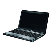
Toshiba Satellite Pro PROA660 Series Manuals
Manuals and User Guides for Toshiba Satellite Pro PROA660 Series. We have
1
Toshiba Satellite Pro PROA660 Series manual available for free PDF download: Maintenance Manual
Toshiba Satellite Pro PROA660 Series Maintenance Manual (301 pages)
Personal Computer Satellite & Satellite Pro
Brand:
Toshiba
| Category:
Laptop
| Size: 10.72 MB
Table of Contents
Table of Contents
6
Troubleshooting Procedures
4
Table of Contents
6
Table of Contents
11
Chapter 1 Hardware Overview
14
Features
18
Inch HDD
28
DVD Super Multi (+-R Double Layer)
29
Power Supply
31
Batteries
33
Battery Charging Control
33
Main Battery
33
RTC Battery
34
Chapter 2 Troubleshooting Procedures
35
Modem Troubleshooting Process
36
Express Card Troubleshooting Process
36
Troubleshooting Introduction
38
Troubleshooting Flowchart
39
Power Supply Troubleshooting
45
Display Troubleshooting
51
Keyboard Troubleshooting
54
External USB Devices Troubleshooting
56
Touchpad Troubleshooting
60
Speaker Troubleshooting
62
Optical Drive Troubleshooting
64
Modem Troubleshooting
67
Express Card Troubleshooting
70
Wireless LAN Troubleshooting
73
Camera Troubleshooting
76
Bluetooth Troubleshooting
78
Bridge Media Slot Troubleshooting
81
HDD/SSD Troubleshooting
84
CRT Failure Troubleshooting
86
HDMI Troubleshooting Process
88
HDMI CEC Troubleshooting
88
MIC Troubleshooting
90
Finger Print Troubleshooting
92
E-SATA Troubleshooting
94
E-SATA Troubleshooting Process
95
Felica Troubleshooting
97
JET Troubleshooting
99
Sensor Troubleshooting Process
102
Sleep & Charge Troubleshooting
105
CIR Troubleshooting
108
Sleep & Play Music Troubleshooting
110
Wimax Troubleshooting
112
Troubleshooting
114
LAN Troubleshooting
117
Ambient Light Sensor Troubleshooting
119
Chapter 3 Tests and Diagnostics
122
Audio Sound Test
122
Display Configuration
122
Executing the Diagnostic Test
122
The Diagnostic Test
122
The Diagnostic Test
123
Audio Sound Test
124
Fan ON/OFF Test
124
Executing the Diagnostic Test
124
Audio Sound Test
127
Display Configuration
127
Main Battery Charge Test
132
FDD Test
135
Memory Check
136
Keyboard Test
139
Mouse (Pad) Test
141
LCD Pixels Mode Test
142
Magnetic Switch Test
143
LAN Test
145
RTC Test
146
BUTTON Test
147
Read DMI
151
Write DMI
152
Sensor Test
154
TP TYPE R/W Test
158
EEPROM Setting
161
Toshiba Logo Set
166
Dynabook Logo Set
168
Chapter 4 Replacement Procedures
170
Table of Contents
171
General
176
Inverter Board
177
Thermal Fan
177
Wlan Card
177
Safety Precautions
178
Before You Begin
180
Assembly Procedures
181
Disassembly Procedures
181
Screw Tightening Torque
182
Tools and Equipment
182
Colors of Screw Shanks
183
Symbol Examples
183
Symbols of Screws on the Laptop Body
183
Battery
184
Figure 4.1 Removing the Battery Pack
184
Removing the Battery Pack
184
Installing the Battery Pack
185
Figure 4.2 Removing the HDD Door
186
Hdd
186
Removing the HDD
186
Figure 4.3 Releasing the HDD from the Connector
187
Figure 4.4 Removing the HDD from the HDD Bay
187
Figure 4.5 Removing the HDD Foil
188
Installing the HDD
188
Figure 4.6 Securing the HDD Foil
189
Figure 4.7 Removing the RAM Door
190
Memory
190
Removing the Optional Memory
190
Figure 4.8 Removing the RAM from the Connectors
191
Installing the Optional Memory
191
Figure 4.9 Removing the Keyboard
192
Keyboard
192
Removing the Keyboard
192
Figure 4.10 Releasing the Keyboard
193
Figure 4.11 Raising the Keyboard
193
Figure 4.12 Disconnecting the Cables and Removing the Keyboard
194
Installing the Keyboard
194
Figure 4.13 Removing the TV Tuner Card
195
Removing the TV Tuner Card
195
TV Tuner Card and WLAN Card
195
Figure 4.14 Removing the WLAN Card
196
Installing the TV Tuner Card
196
Removing the WLAN Card
196
Installing the WLAN Card
197
ODD Module (Tray-Load)
198
Removing the ODD Module (Tray-Load)
198
Disassembling the ODD (Tray-Load)
199
Installing the ODD Module (Tray-Load)
199
Assembling the ODD (Tray-Load)
200
Figure 4.18 Removing Thirteen Screws from the Bottom of the Laptop
201
Logic Upper Assembly
201
Removing the Logic Upper Assembly
201
Figure 4.19 Disconnecting the Cables and Removing the Upper Logic Assembly Screw
202
Figure 4.20 Removing the Logic Upper Assembly
202
Installing the Logic Upper Assembly
203
ODD Module (Slot-Load)
204
Installing the ODD Module (Slot-Load)
204
Removing the ODD Module (Slot-Load)
204
Disassembling the ODD (Slot-Load)
205
Figure 4.21 Disassembling the Slot-Load ODD
205
Assembling the ODD (Slot-Load)
206
Felica Card
207
Figure 4.22 Removing the Felica Card from the Logic Upper Assembly
207
Installing the Felica Card
207
Removing the Felica Card
207
Figure 4.23 Raising the Fingerprint Scanner Bracket from the Logic Upper Assembly
208
Fingerprint Scanner Bracket
208
Removing the Fingerprint Scanner Bracket
208
Figure 4.24 Working the Fingerprint Scanner Bracket Loose
209
Figure 4.25 Removing the Fingerprint Scanner Bracket from the Logic Upper Assembly
209
Installing the Fingerprint Scanner Bracket
210
Figure 4.26 Removing the Touch Pad Board
211
Installing the Touch Pad Board
211
Removing the Touch Pad Board
211
Touch Pad Board
211
Figure 4.27 Removing the Speakers
212
Removing the Speakers
212
Speakers and Speaker Cushions
212
Figure 4.28 Removing the Speaker Cushions
213
Installing the Speaker Cushions
213
Installing the Speakers
213
Removing the Speaker Cushions
213
Figure 4.29 Removing the Indicator Board
214
Indicator Board
214
Installing the Indicator Board
214
Removing the Indicator Board
214
Figure 4.30 Removing the USB Board
215
Installing the USB Board
215
Removing the USB Board
215
USB Board
215
Bluetooth
216
Figure 4.31 Removing the Bluetooth
216
Installing the Bluetooth
216
Removing the Bluetooth
216
Figure 4.32 Removing the Thermal Fan
217
Installing the Thermal Fan
217
Removing the Thermal Fan
217
Thermal Fan
217
Figure 4.33 Removing the TV Tuner Antenna
218
Installing the TV Tuner Antenna
218
Removing the TV Tuner Antenna
218
TV Tuner Antenna
218
Figure 4.34 Removing the Power Membrane
219
Installing the Power Membrane
219
Power Membrane
219
Removing the Power Membrane
219
Display Assembly
220
Figure 4.35 Removing the Display Assembly
220
Removing the Display Assembly
220
Installing the Display Assembly
221
Figure 4.36 Removing the DC in Cable from the Connector Slot
222
Removing the Motherboard Assembly
222
Figure 4.37 Removing the Discreet Motherboard from the System
223
Installing the Motherboard
223
Figure 4.38 Removing the Thermal Module (Discrete Model)
224
Removing the Thermal Module
224
Thermal Module
224
Figure 4.39 Removing the Thermal Module (UMA Model)
225
Figure 4.40 Reapplying Shinetsu 7762 Grease on the Thermal Module and Remove any Release
226
Installing the Thermal Module
226
Figure 4.41 Installing the Thermal Module (Discrete Model)
227
Figure 4.42 Reapplying Shinetsu 7762 Grease on the Thermal Module and Remove any Release Papers
227
Figure 4.43 Installing the Thermal Module (UMA Model)
228
Cpu
229
Figure 4.44 Removing the CPU
229
Removing the CPU
229
Installing the CPU
230
Figure 4.45 Removing Four Screws Securing the LCD Bezel to the Display Assembly
231
LCD Bezel
231
Removing the LCD Bezel
231
Figure 4.46 Prying up the LCD Bezel from the Outside Edges
232
Installing the LCD Bezel
233
Figure 4.47 Removing the LCD Panel from the Display Assembly
234
LCD Panel
234
Removing the LCD Panel
234
Figure 4.48 Disconnecting the Webcam
235
Installing the LCD Panel
235
Figure 4.49 Removing the Web Camera from the Display Assembly
236
Installing the Web Camera
236
Removing the Web Camera
236
Web Camera
236
Figure 4.50 Removing the WLAN Antennas from the Display Assembly
237
Removing the WLAN Antennas
237
WLAN Antennas
237
Figure 4.51 Routing the WLAN Antennas Onto the Display Assembly
238
Installing the WLAN Antennas
238
Figure 4.52 Removing the LCD Panel Hinges from the LCD Panel
239
Installing the LCD Panel Hinges
239
LCD Panel Hinges
239
Removing the LCD Panel Hinges
239
Figure 4.53 Removing the LVDS Cable from the LCD Panel
240
Installing the LVDS Cable
240
LVDS Cable
240
Removing the LVDS Cable
240
Appendix A Handling the LCD Module
241
Appendix B Board Layout
246
Appendix C Pin Assignments
254
System Board
254
Appendix E Key Layout
282
Appendix G Reliability
301
Advertisement
Advertisement
Related Products
Toshiba Satellite Pro T110
Toshiba Satellite Pro L300
Toshiba Satellite Pro R50-E Series
Toshiba Satellite Pro A50-E Series
Toshiba PSAF4U-00L004
Toshiba PX35t
Toshiba Qosmio PX30t Series
Toshiba PX30 - A Series
Toshiba PORTEGE T110
Toshiba PX30t-01E
Toshiba Categories
Laptop
Air Conditioner
TV
LCD TV
All in One Printer
More Toshiba Manuals
Login
Sign In
OR
Sign in with Facebook
Sign in with Google
Upload manual
Upload from disk
Upload from URL