Sign In
Upload
Manuals
Brands
Yamaha Manuals
Motorcycle
1970 G5G
Yamaha 1970 G5G Manuals
Manuals and User Guides for Yamaha 1970 G5G. We have
1
Yamaha 1970 G5G manual available for free PDF download: Service Manual
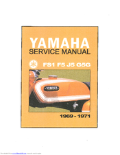
Yamaha 1970 G5G Service Manual (95 pages)
Brand:
Yamaha
| Category:
Motorcycle
| Size: 46.28 MB
Table of Contents
Contents
4
Features
7
Specifications
8
Tools and Instruments for Shop Service
10
Yamaha Autolube
12
Handling the Oil Pump: Checking and Adjusting the Minimum Pump Stroke
12
Handling the Oil Pump: Checking and Adjusting the Setting of the Pump and Carburetor
13
Removing the Engine
15
Cylinder Head: Removal and Reinstallation
18
Cylinder Head: Removing Carbon
19
Cylinder: Checking Cylinder Wear
19
Cylinder: Measuring Positions of the Bore
19
Minimum Clearance between Piston and Cylinder
19
Cylinder Reconditioning
20
Installing Cylinders
20
Driving out the Piston Pin
20
Piston-To-Piston Pin Fit
20
Piston Rings: Removing Rings
21
Piston Rings: Fitting the Rings
21
Piston Rings: Checking Piston Rings
21
Checking and Reconditioning the Piston
22
Installing the Piston in Its Proper Direction
23
Crankcase Cover: Removal
23
Crankcase Cover: Reinstallation
24
Clutch
25
Clutch: Removing the Pressure Plate
26
Clutch: Checking Clutch Springs
26
Clutch: Removing the Clutch Boss
26
Clutch: Checking the Friction Plates
26
Clutch: Checking the Primary Gear Spacer
27
Clutch: Adjusting the Clutch
27
Clutch: Caution on Reassembling the Clutch
27
Primary Drive Gear: Removal
28
Kickstarter: Removal
29
Kickstarter: Kick Cross Section
29
Exploded View of the Kickstarter
30
Kickstarter: Removing the Kick Idler Gear
31
Shifting Mechanism: Construction and Operation
32
Shifting Mechanism: Removing the Change Axle Ass'y
32
Shifting Mechanism: Checking Change Axle Parts
33
Shifting Mechanism: Gear Shift Arm
33
Rotary Valve: Removal
33
Rotary Valve: Checking
34
Drive Sprocket: Removal
35
Checking the Drive Sprocket
36
Splitting the Crankcase Halves
36
Reassembling the Crankcase Halves
37
Engine Transmission Assembly: F5/J5 & G5G Exploded View of Transmission
38
Engine Transmission Assembly: FS1 Exploded View of Transmission
39
Engine Transmission Assembly: Removal
40
Engine Transmission Assembly: Rreinstallation
40
Engine: Crankshaft
41
Engine: Crankshaft Components
41
Engine: Dimensions of Crankshaft Ass'y
41
Engine: Removing the Crankshaft Ass'y
41
Engine: Reinstalling the Crankshaft Ass'y
42
Engine: Crankshaft Checking and Servicing
42
Engine Bearing and Oil Seals: Removal and Reinstallation
43
Checking the Carburetor
44
Reconditioning the Carburetor
44
Carburetor Setting
45
Air Cleaner: Removal
46
Air Cleaner: Cleaning
46
Transmission Oil
46
Chassis: Front Wheel
47
Chassis: Front Wheel: Removal
48
Chassis: Front Wheel: Checking
48
Chassis: Front Wheel: Brake Show
49
Chassis: Front Wheel: Brake Drum
49
Chassis: Rear Wheel: Construction View
49
Chassis: Rear Wheel: Removal
50
Chassis: Rear Wheel: Checking
51
Chassis: Front Fork
51
Chassis: Front Fork: Disassembling the Fork
52
Chassis: Front Fork: Checking
54
Chassis: Front Fork: Reassembling
54
Rear Cushion: Checking Oil Leakage
55
Steering Head: Checking
55
Electrical Equipment
56
List of Electrical Components
56
Connection Diagram
57
Ignition System-Function and Service
57
Service Standards: Ignition Timing & Point Gap
58
Service Standards: Ignition Coil
58
Service Standards: Condenser
59
Function of the Charging System
60
Checking the Charging System
60
Checking the Silicon Rectifier
61
Magneto Output Voltage
61
Checking the Main Switch (Removed from the Chassis)
62
Battery: Checking
63
Battery: Service Life/Service Standards
63
Battery: Storage
63
How to 'Read' Spark Plug (Condition)
63
Spark Plug: Inspection
64
Standard Spark Plug
64
Chart of Wire Colors
65
Model F5/J5 Circuit Diagram
66
Model FS1 Circuit Diagram
68
Conversion Table
69
Torque Specifications
69
Millimeters to Inches
70
Inches to Millimeters
70
Model 50 FS1: Supplementary Service Information
71
Model 50 FS1: Features
74
Model 50 FS1: Specifications and Performance
75
Model 50 FS1: External View
77
Model 50 FS1: Performance Curves
78
Model 50 FS1: Engine: Cylinder & Piston
79
Model 50 FS1: Engine: Air Cleaner
80
Model 50 FS1: Engine: Crankcase and Crankcase Cover
80
Model 50 FS1: Engine: Muffler and Protector
80
Model 50 FS1: Engine: Kick Starter
80
Model 50 FS1: Engine: Transmission Assembly
81
Model 50 FS1: Engine: Shifter Assembly
81
Model 50 FS1: Engine: Clutch Assembly
81
Model 50 FS1: Chassis
82
Model 50 FS1: Chassis: Front Fork Assembly
83
Model 50 FS1: Chassis: Handle Grips
83
Model 50 FS1: Chassis: Brake Pedal and Foot Rest
83
Model 50 FS1: Chassis: Front/Rear Wheels
83
Model 50 FS1: List of Electrical Parts
84
Model 50 FS1: Principal Electrical Modifications
85
Model 50 FS1: Connection Diagram
85
Model 50 FS1: Checking of Parts
85
Model 50 FS1: Sparking
86
Model 50 FS1: Insulation Resistance Test
87
Model 50 FS1: Capacity Test
87
Model 50 FS1: Checking the Silicon Rectifier
88
Model 50 FS1: Magneto Output Voltage
88
Model 50 FS1: Inspecting Wiring and Switch Connection
89
Model 50 FS1: Checking the Main Switch Removed from the Chassis
89
Model 50 FS1: Battery Service Data
90
Model 50 FS1: Service Data
91
Model 50 FS1: Wiring Diagram
93
Advertisement
Advertisement
Related Products
Yamaha 1970 FS1
Yamaha 1970 J5
Yamaha 1970 F5
Yamaha 1970 HS1-B
Yamaha 1970 HS1
Yamaha 1970 CS3-C
Yamaha 1970 DS6-B
Yamaha 1970 R5
Yamaha 1972 DS7
Yamaha 1973 RD250
Yamaha Categories
Motorcycle
Musical Instrument
Electronic Keyboard
Receiver
Amplifier
More Yamaha Manuals
Login
Sign In
OR
Sign in with Facebook
Sign in with Google
Upload manual
Upload from disk
Upload from URL