Sign In
Upload
Manuals
Brands
Yamaha Manuals
Outboard Motor
30X
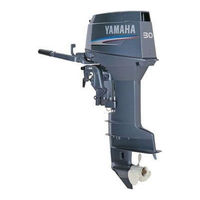
User Manuals: Yamaha 30X Midrange Outboard Motor
Manuals and User Guides for Yamaha 30X Midrange Outboard Motor. We have
2
Yamaha 30X Midrange Outboard Motor manuals available for free PDF download: Service Manual, Owner's Manual
Yamaha 30X Service Manual (385 pages)
Brand:
Yamaha
| Category:
Outboard Motor
| Size: 7.74 MB
Table of Contents
How to Use this Manual
4
Important Information
6
Symbols
10
Index
12
Table of Contents
14
General Information
14
Identification
16
Serial Number
16
Starting Serial Numbers
16
Chapter 1
16
Safety While Working
18
Fire Prevention
18
Ventilation
18
Self-Protection
18
Oils, Greases and Sealing Fluids
18
Good Working Practices
20
Disassembly and Assembly
22
Measuring
24
Special Tools
24
Outillage Special
25
90890-03169
27
90890-06752
27
90890-06754
27
P/N. J-39299
27
P/N. Ym-34487
27
P/N. Yu-39991
27
Removal and Installation
28
Specifications
32
Chapter 2
34
General Specifications
34
Maintenance Specifications
42
Caracteristiques D'entretien
43
Moteur
43
Bloc de Propulsion
47
Electrical
48
Partie Electricite
49
Bracket Dimensions
52
Outboard Dimensions
52
Dimensions du Moteur Hors-Bord
53
Dimensions du Support
53
Daten
53
Dimensiones de la Ménsula
53
Dimensiones del Fuera de Borda
53
Wartungdaten
53
Especificaciones de Mantenimiento
53
Tightening Torque
54
Torsión de Apriete
55
General Tightening Torque
56
Torsiones de Apriete
57
Periodic Inspection and Adjustment
58
Predelivery Service
62
Contents
62
Electric Wiring
64
Chapter 3
64
25Jmh, 25Jmho, 30Dmh, 30Dmho
64
30Dwh, 30Dwho
66
25Jeo, 30Dmo, 30De, 30Deo
68
25Jeto, 30Det, 30Deto
70
Fuel Line
72
Gear Oil Level
74
Operation of Controls and Moving Parts
74
Ignition Timing
76
Motor Exterior
76
Instructing the New Owner
76
Fuel Leakage
76
Water Leakage
76
Exhaust Leakage
76
Engine and Lower Unit Noise
76
Idle-Speed
76
Periodic Service
78
Maintenance Schedule
78
Anode
78
Battery
82
Cylinder Head Bolts, Engine Mounting Bolts, and Flywheel Nut
84
Gear Oil
84
Oil-Injection Pump
84
Operational Test
84
Fuel Filter
84
Fuel Line
84
Carburetor
86
Carburetor Link Adjustment
88
Fuel Enrichment Valve Adjustment
88
Ignition Timing Adjustment
88
Idle-Speed
92
Oil Pump Link Adjustment
94
Pick-Up Timing
94
25Jeo, 25Jeto, 30Deo, 30Deto
96
25Jmho, 30Dmo, 30Dmho, 30Dwho
96
Oil-Level Warning System
96
Propeller
96
Spark Plug
98
Manual Handle Model
100
Start-In-Gear Protection Adjustment
100
Start-In-Gear Protection Model
100
Throttle Cable Adjustment
100
Neutral Opening Limit Adjustment
102
Power Trim and Tilt Fluid Check
102
Hydraulic System Air Bleeding
104
Fuel System
106
Fuel System Exploded Diagram
108
Fuel Filter Cleaning and Inspection
110
Removal
110
Fuel Joints
112
Installation
112
Carburetor Exploded Diagram
114
Carburetor Removal and Disassembly
116
Carburetor Body
118
Collar
118
Float
118
Inspection
118
Needle Valve
118
Pilot Screw
118
Fuel Pump
120
Assembly
122
Installation
124
Oil Injection Exploded Diagram
126
Installation
128
Oil Injection Cleaning and Inspection
128
Oil-Hoses
128
Oil-Level Gauge
128
Oil-Tank
128
Oil Injection Removal
128
Power Unit
130
Exploded Diagram
134
CHAPTER 5 Preparation for Overhaul
136
Removal
136
Disassembly
138
Cylinder Head
140
Inspection
140
Cleaning
140
Cylinder Block
142
Cleaning
142
Inspection
142
Piston Cleaning
144
Piston Inspection
144
Inspection
146
Piston Ring
146
Cleaning
148
Crankshaft
148
Inspection
148
Piston Pin and Small End Bearing
148
Inspection
150
Reed Valve
150
Thermostat
150
(Oil Injection Pump Drive)
152
Cleaning
152
Crank Main Bearing
152
Drive Gear
152
Driven Gear (Oil Injection Pump Drive)
152
Inspection
152
Bearing, Oil Seal, O-Ring and Oil Pump Drive Gear
154
Assembly and Adjustment
154
Piston
154
Crank Cylinder Assembly
156
Small End Bearings and Piston Assembly
156
Cylinder Head and Exhaust Cover
158
Fuel System and Electrical System
160
Installation
160
Intake Manifold
160
Reed Valve
160
Recoil Starter Exploded Diagram
162
Drive Pawl and Spring
164
Inspection
164
Removal and Disassembly
164
Collar and Roller
166
Sheave Drum
166
Starter Rope
166
Start-In-Gear Protection
168
Starter Spring
168
Lower Unit
174
Lower Unit Exploded Diagram
178
Preparation for Removal
180
Disassembly
180
Bearing Housing
190
Claw-Washer
190
Gear Case
190
Inspection
190
Ring-Nut
190
Water Pump Housing
190
Bearing
192
Clutch Dog and Components
192
Gear
192
OIL-SEAL HOUSING (Located under the Impeller)
192
Drive Shaft and Propeller Shaft
194
Drive Shaft Sleeve
194
Propeller/Trim Tab/Anode
194
Shift-Plunger, Shift-Shaft, and Boot
194
Forward Gear Shim Selection
196
Pinion Gear Shim Selection
196
Propeller-Shaft Housing
196
Assembly and Adjustment
196
Impeller and Cartridge Insert
192
Assembly
196
Gear Case
198
Reverse Gear Shim Selection
198
SHIM SELECTION (for USA and CANADA)
202
Pinion Gear Shim
204
Forward Gear Shim
206
Reverse Gear Shim
210
SHIM SELECTION (Except for USA and CANADA)
212
Forward Gear Shim
216
Reverse Gear Shim
218
Forward Gear
220
Measuring the Backlash
220
Reverse Gear
222
Water Pump Installation
224
Lower Unit Leakage Check
226
Bracket Unit
230
Steering Handle Exploded Diagram
234
Steering Handle Removal and Installation Chart
234
Bottom Cowling Exploded Diagram
236
Bottom Cowling Removal and Installation Chart
236
Upper Case Exploded Diagram
240
Upper Case Removal and Installation Chart
240
Steering Bracket Exploded Diagram
246
Steering Bracket Removal and Installation Chart
246
Power Trim and Tilt (Ptt) Unit Exploded Diagram
250
Power Trim and Tilt (Ptt) Unit Removal and Installation Chart
250
Clamp Bracket Exploded Diagram
254
Clamp Bracket Removal and Installation Chart
254
Clamp Bracket (Except Ptt Model)
254
Clamp Bracket (Ptt Model)
260
Swivel Bracket Exploded Diagram
264
Swivel Bracket Removal and Installation Chart
264
Tilt Rod Exploded Diagram
268
Tilt Rod Removal and Installation Chart
268
Service Points
272
Tilt Rod Removal
272
Tilt Piston Installation
274
Tilt Rod Installation
274
Air Bleeding
276
Ptt Motor, Pump Housing, and Tilt Cylinder Exploded Diagram
280
Pump Housing Exploded Diagram
284
Pump Housing Removal and Installation Chart
284
Gear Pump Exploded Diagram
290
Gear Pump Removal and Installation Chart
290
Motor Inspection
296
PTT Motor Assembly
298
Electrical Systems
300
Chapter 8
304
Electrical Components
304
Jeho, 30Dwh, 30Deho
306
Wire Harness
312
Flywheel Magneto Removal
316
Flywheel Magneto Installation
320
Electrical Analysis
322
Digital Circuit Tester
322
Peak Voltage Adaptor
322
Ignition System
326
Peak Voltage Measurement
322
Ignition Spark Gap
328
Ignition System Peak Voltage
330
Engine Stop Switch
332
Ignition Control System
334
Spark Plug Cap
332
Oil Level Gauge
336
Pulser Coil
336
Thermo Switch
336
Oil Level/Engine Temp. Warning Lamp
338
Starting System
340
Fuse
342
Starter Relay
342
Wire Connections
342
Neutral Switch
344
Starter Switch
344
Fuel Enrichment Valve
346
Starter Motor Exploded Diagram
348
Starter Motor Removal and Installation Chart
348
Armature Inspection
352
Pinion Inspection
352
Brush Holder Inspection
354
Rear Bracket Bushing Inspection
354
Charging System
356
Charging System Peak Voltage
358
Power Trim and Tilt (Ptt) Control System
360
Ptt Relay
362
Trim Sensor
364
Trouble Analysis
366
Trouble Analysis Chart
368
Advertisement
Yamaha 30X Owner's Manual (132 pages)
Yamaha Outboards
Brand:
Yamaha
| Category:
Outboard Motor
| Size: 18.76 MB
Advertisement
Related Products
Yamaha 30B
Yamaha 30A
Yamaha 30Z
Yamaha 30D
Yamaha 30HWC
Yamaha 30ELRZ
Yamaha 30MLHZ
Yamaha 30MSHZ
Yamaha 30DET
Yamaha 30
Yamaha Categories
Motorcycle
Musical Instrument
Electronic Keyboard
Receiver
Amplifier
More Yamaha Manuals
Login
Sign In
OR
Sign in with Facebook
Sign in with Google
Upload manual
Upload from disk
Upload from URL