Advertisement
Table of Contents
thank you for purchasing a sealey product. manufactured to a high standard, this product will, if used according to these
instructions, and properly maintained, give you years of trouble free performance.
IMPORTANT: PLEASE READ THESE INSTRUCTIONS CAREFULLY. NOTE THE SAFE OPERATIONAL REQUIREMENTS, WARNINGS & CAUTIONS. USE
THE PRODUCT CORRECTLY AND WITH CARE FOR THE PURPOSE FOR WHICH IT IS INTENDED. FAILURE TO DO SO MAY CAUSE DAMAGE AND/OR
PERSONAL INJURY AND WILL INVALIDATE THE WARRANTY. KEEP THESE INSTRUCTIONS SAFE FOR FUTURE USE.
refer to
electrical
instructions
shock
hazard
1. safety
1.1.
Personal PreCautions
When using this meter, please observe all normal safety rules concerning:
9
Protection against the dangers of electric current.
Protection of the meter against misuse.
full compliance with safety standards can only be guaranteed if used with the test leads supplied. if necessary, they must be replaced
9
with genuine sealey leads with the same electronic ratings. failure to do so will invalidate the warranty.
do not use leads if damaged or if the wire is bared in any way.
8
1.2.
general safety instruCtions
familiarise yourself with the applications, limitations and hazards of the meter. if in any doubt consult a qualified electrician.
9
When the meter is linked to a measurement circuit, do not touch unused meter terminals.
9
When the scale of the value to be measured is unknown set the selector to the highest range available.
9
Before rotating the range selector to change functions, disconnect test leads from the circuit under test.
9
Warning! never perform resistance measurements on live circuits.
‰
Always be careful when working with voltages above 60Vdc or 30Vac rms. Keep your fingers behind the probe guards while measuring.
9
When not in use, store the meter carefully in a safe, dry, childproof location. storage temperature range -10°c to 50°c
9
do not apply voltage or current to the meter that exceeds the specified maximum.
8
the user shall ensure that test probes are correctly selected in order to prevent danger. Probes shall be selected to ensure that
9
adequate barriers guard against inadvertent hand contact with live conductors under test and that probes have minimal exposed
probe tips. Where there is a risk of the probe tip short circuiting with other live conductors under test, it is recommended that the
exposed tip length shall not exceed 4mm.
2.
Per ieC1010 overvoltage installation Category
2.1.
overvoltage category i
equipment of overvoltage category i is equipment for connection to circuits in which measures are taken to limit the transient
overvoltages to an appropriate low level.
note – examples include protected electronic circuits.
2.2.
overvoltage category ii
Equipment of overvoltage category II is energy-consuming equipment to be supplied from the fixed installation.
note – examples include household, office, and laboratory appliances.
2.3.
overvoltage category iii
Equipment of overvoltage category III is equipment in fixed installations.
note – examples include switches in the fixed installation and some equipment for industrial use with permanent connection to the
fixed installation.
2.4.
overvoltage category iV
equipment of overvoltage category iV is for use at the origin of the installation.
note – examples include electricity meters and primary over-current protection equipment
3. introduCtion
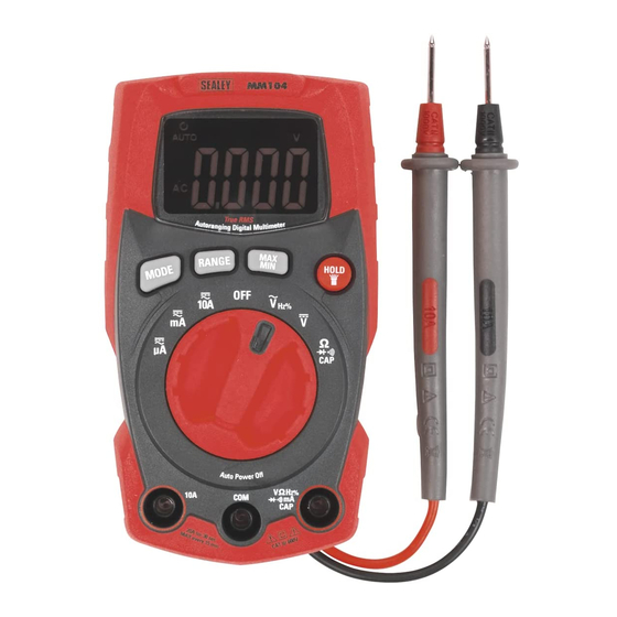
lightweight, compact digital multimeter with double moulded plastic housing and a 4000 counts lcd display. drop-proof up to 2mtr. iP65
rated as "dust tight" and protected against low pressure water jets (all directions). features display back light and forward facing work light.
conforms to en 61010-1 and en 61010-2-033ncAtiii 600V safety requirements for electrical equipment for measurement, control and
laboratory use. measures: Ac and dc Voltage, Ac and dc current, resistance, frequency, duty cycle, diode test, continuity test and
capacitance.
© Jack sealey limited
instructions for
Professional auto-ranging digital
multimeter
mm104
model no:
Original Language Version
mm104 | issue 1 13/09/16
Advertisement
Table of Contents

Summary of Contents for Sealey MM104
- Page 1 IMPORTANT: PLEASE READ THESE INSTRUCTIONS CAREFULLY. NOTE THE SAFE OPERATIONAL REQUIREMENTS, WARNINGS & CAUTIONS. USE THE PRODUCT CORRECTLY AND WITH CARE FOR THE PURPOSE FOR WHICH IT IS INTENDED.
-
Page 2: Specification
(drop test)..........6.5 feet (2 meters) transistor test.............no diode test............Yes continuity Check..........Audible signal will sound if the resistance is less than 50Ω (approx.), test current <0.35mA temperature sensor...........requires type K thermocouple input Impedance..........>10MΩ VDC & >10MΩ VAC Ac response.............trms AcV Bandwidth..........50/60HZ(All WAVe) 45Hz to 1000Hz(sine WAVe) Original Language Version mm104 | issue 1 13/09/16 © Jack sealey limited... -
Page 3: Operation
5.2.1. set the function switch to the VAc/Hz/% position. Original Language Version mm104 | issue 1 13/09/16 © Jack sealey limited... - Page 4 Ω CAP position. 5.8.2. insert the black test banana plug into the negative com jack and the red test iead banana plug into the positive V jack. Original Language Version mm104 | issue 1 13/09/16 © Jack sealey limited...
-
Page 5: Maintenance
Warning! to avoid electric shock do not operate the meter until the fuse cover is in place and fastened securely. ‰ Original Language Version mm104 | issue 1 13/09/16 © Jack sealey limited... - Page 6 Battery removal see section 6.2 under the Waste Batteries and Accumulators regulations 2009, Jack sealey ltd are required to inform potential purchasers of products containing batteries (as defined within these regulations), that they are registered wih Valpak’s registered compliance scheme. Jack Sealey Ltd’s Batteries Producer Registration Number (BPRN) is BPRN00705. NOTE: It is our policy to continually improve products and as such we reserve the right to alter data, specifications and component parts without prior notice.


