Sign In
Upload
Manuals
Brands
Canon Manuals
All in One Printer
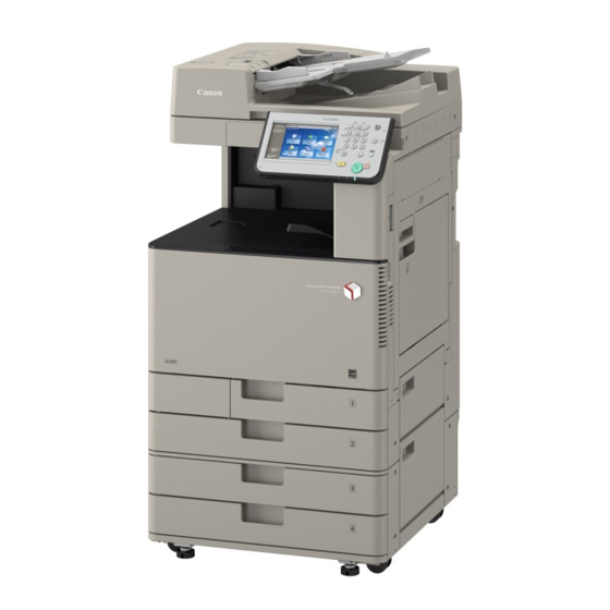
imageRUNNER ADVANCE C3330 Series
Canon imageRUNNER ADVANCE C3330 Series Manuals
Manuals and User Guides for Canon imageRUNNER ADVANCE C3330 Series. We have
6
Canon imageRUNNER ADVANCE C3330 Series manuals available for free PDF download: Service Manual, Troubleshooting Manual, Service Information, Replacement Procedure
Canon imageRUNNER ADVANCE C3330 Series Service Manual (952 pages)
Brand:
Canon
| Category:
All in One Printer
| Size: 46.44 MB
Table of Contents
Explanation of Symbols
3
Table of Contents
4
Option ---------------------------------------------------------------------------------
9
Safety Precautions
11
Laser Safety
11
Handling of Laser System
11
Turn Power Switch on
11
Laser Safety
12
Handling of Laser System
12
Turn Power Switch on
13
Power Supply
13
Safety of Toner
13
About Toner
13
Toner on Clothing or Skin
13
Notes When Handling a Lithium Battery
14
Notes before It Works Serving
14
Points to Note at Cleaning
14
Notes on Assembly/Disassembly
14
Points to Note When Tightening a Screw
15
Product Overview
16
Product Lineup
16
Host Machine
17
Positioning
17
Product Lineup
17
Option
18
Pickup / Delivery / Image Reading System Options
18
Function Expansion System Options
19
Characteristics
20
Product Features
20
Toner Container
20
Improved Replaceability of Consumables
21
Item Numbers of Consumables Specified on Host Machine
21
Drum Unit
22
Maintenance Video for Consumables Replacement
23
Setup Guide
23
Introduction of Situation Mode
24
Limiting of Color Printing
24
Specifications
25
Weight and Size
26
Productivity
26
Paper Type
27
Pickup
28
Parts Name
36
Cross Sectional View
36
Control Panel
36
Technical Explanation
37
Basic Configuration
37
Basic Configuration
38
Functional Configuration
38
Document Exposure
39
Cross Section
39
External View
39
Major Electrical Parts
40
Scanner Unit
40
LED Lamp Unit
41
Reader Heater
41
Reading Sensor
41
Controls
42
Image Processing
42
Reading Speed
42
Shading Correction
42
Dust Detection / Correction Control
43
Change of Magnification Ratio
44
Color Displacement Correction in Vertical Scanning Direction
44
Original Size Detection
44
Description of Controls
45
MTF Adjustment
45
Service Mode/Adjustment
45
Service Tasks
45
Main Controller
46
Configuration / Function
46
Main Controller PCB
46
Overview
46
Boot Sequence
47
Shutdown Sequence
47
Controls
48
Copy
48
Network(Advanced Box / Space Client)
48
Print
48
Send
48
Fax Receive
49
Fax SEND
49
Complete Deletion of Hard Disk Data
50
Initialize All Data/Settings
50
Management Settings of Hard Disk
50
Security
50
Security Function (Encryption Key, Certificate and Protection of Password)
51
Security Information Structure
51
TPM Settings of Security Information
52
Works to be Done before and after Introduction
52
Enabling of the Function
53
Backup of TPM Key
54
Restoration of TPM Key
55
Disabling of the Function
56
Target Data for Encryption/Decryption (Reference)
57
Conditions of Encryption Board Operation
58
Data Encryption System
58
Hard Disk Encryption Function
58
HDD Encryption Kit (Option)
58
Overview of Countermeasures for Trouble
59
Laser Exposure System
60
Overview
60
Specification
61
1-Polygon 4-Laser Method
62
Control Description
63
Execution Timing
63
Laser ON/OFF Control
63
Purpose
63
Horizontal Scanning Synchronous Control
64
Vertical Scanning Synchronous Control
65
Image Mask Control
66
Laser Scanner Motor Control
66
Apc(Auto Power Control) Control
67
BD Correction Control
68
Image Formation System
69
Overview
69
Parts Configuration
69
Print Process
70
Bias Types
71
Controls
72
Drum Unit / Developing Unit
72
Drum Cleaning / Drum Cleaning Pre-Exposure Control
73
Drum Unit Detection
74
Drum Unit Life Detection
74
Primary Charging
75
Transfer/Separation
76
Primary Transfer Bias Control
77
Primary Transfer Control
77
Primary Transfer Roller Disengagement Control
78
Secondary Transfer ATVC
78
Secondary Transfer Bias Control
78
Secondary Transfer Control
78
Primary Transfer Disengagement Initialization
79
Status of each Mode/Timing to Enter each Mode
79
ITB Cleaning
80
ITB Displacement Correction
80
Secondary Transfer Outer Roller Cleaning Control
81
Control Timing List
82
Image Stabilization Control
82
ARCDAT Control
83
Color Displacement Correction Control
83
D-Half Control
83
Laser Power Correction (D-Max) Control
83
Configuration of the Patch Sensor
84
Light Intensity Adjustment
84
Patch Sensor Adjustment
84
Sampling of the ITB Background
84
Auto Gradation Adjustment (PASCAL) Control
85
Toner Supply Area
85
Bottle State Detection
86
Opening/Closing of Toner Container Shutter
86
ATR (Auto Toner Replenishment) Control
87
Toner Container Detection
87
Toner Supply Control
88
Detection of Completion of Toner Replacement
90
Toner Level Detection
90
Waste Toner Container Full Level Detection
91
Waste Toner Feed Unit
91
Detection of Completion of Waste Toner Replacement
92
Other Controls
92
Special Controls
92
Waste Toner Container Detection
92
Behavior When Color Printing Is Limited or There Is no Color Toner
93
Transparency Black Band Sequence
93
Warm-Up Rotation Control
93
Fixing System
94
Overview
94
Major Components
95
Flying Start
96
Overview of Fixing Temperature Control
96
Print Temperature Control
96
Standby Temperature Control
96
Startup (Initial Rotation) Temperature Control
97
Temperature Control by Extended Initial Rotation
97
Paper Interval Temperature Control
98
Down Sequence Control
99
Down Sequence When Feeding Small-Size Paper
99
Down Sequence When Using Paper of Mixed Size and Mixed Type
100
Film Unit Engagement/Disengagement Control
101
Fixing Arch Control
102
Fixing Unit Detection
103
Fixing Unit Life Detection
103
Detection of Whether the Fixing Unit Is New
104
Protection Function
104
Countermeasure When the Fixing Unit Error
105
Pickup / Feed System
106
Overview
106
Layout Drawing of Rollers
107
Layout Drawing of Sensors
107
Diagram of Load Drives
108
Paper Path
109
Controls
110
Cassette Pickup Assembly
111
Cassette Paper Size Detection/Cassette Detection
112
Cassette Pickup Control
112
Lifter Control
112
Paper Level/Presence Detection
115
Multi-Purpose Tray Paper Detection
117
Multi-Purpose Tray Pickup Assembly
117
Multi-Purpose Tray Pickup Control
117
Long Length Paper
118
Multi-Purpose Tray Automatic Size Detection
118
Fixing/Registration Assembly
119
Registration Control
119
Non-Stop Registration Control
120
Reverse / Delivery Assembly
120
Stop Registration Control
120
Jam Detection
122
External Auxiliary System
123
Software Counter Control
123
Count-Up Timing
124
Fan Control
125
Fan Drive Sequence
125
Location of Fans
125
Speed Control
125
Heater Control
126
Internal Power Supply
126
Deep Sleep Mode
127
Energy Saving Function
127
Sleep Standby Mode
127
Standby Mode
127
Conditions for Not Entering Deep Sleep Mode (Check Items)
128
Quick Startup
129
Effect of the Hub Which Supports Spanning Tree
130
Meap
131
Function Overview
131
Login Service and User Authentication Method
131
User Authentication (UA)
131
Network Ports Used
132
OS of the PC and Other Environments
132
PC Environment of Administrator Users and General Users
132
Specification of User Authentication
132
Local Device Authentication
133
Setting the Administrator for Server Authentication
133
System Manager Linkage (Automatic ID Allocation to System Managers)
133
Server Authentication (Active Directory Authentication)
134
Server Authentication (LDAP Authentication)
134
Active Directory Authentication
135
LDAP Authentication
135
User Management with Server Authentication
135
About SMS
136
Default Authentication Overview
136
RLS Authentication
136
User Authentication Methods
136
Password Authentication
137
Checking of Operation Environment
138
Initial Display Languages of SMS
138
PC and Browser Settings
138
Preparation of PC for Accessing SMS
138
About Name
139
MEAP Application Management
139
Mechanism
139
What Is MEAP Specifications (MEAP Spec Version)?
139
Content of MEAP System Information
140
License for Forwarding
140
Reusable License
140
Advantages Obtained When Using the Services
141
MEAP Application Configuration Service
141
MEAP Application Log Service
141
MEAP Application Setting Information Management and Log Management
141
Integrated Authentication Function
142
Persistent Credential
142
Settign Procedure
142
Sharing the Authentication Information
142
Volatile Credential
142
Key Pair and Server Certificate Settings
143
Network Port Change Procedure
143
Procedure to Install Applications
144
Procedure to Start and Stop a MEAP Application
145
Procedure Adding a License File
146
Procedure Disabling a License File (Suspending a License)
147
Procedure Downloading/ Removing an Invalidated License File
148
Procedure for Downloading a License for Forwarding
149
Steps to Change Login Services
150
Login Service Installation Procedure
151
Login Service Uninstallation Procedure
151
Setting the Method to Login to SMS
152
Setting the User Authentication Method
152
Changing SMS Login Password
153
Disabling the Integrated Authentication Function
153
Remote UI
153
License File
155
MEAP Application Information
155
Printing the System Information of a MEAP Application
155
Backup Item Automatically Copied
156
Backup of the MEAP Application Area and Recovery of the Backup Data Using SST
156
Maintenance
156
Outline
156
Formatting and Replacing the HDD
157
Procedure for Backing Up/Restoring the MEAP Application Area
157
Formatting the HDD
158
HDD Replacement Procedure
158
If the MEAP Application Area Can be Backed up
159
Two Types of USB Drivers
159
USB Driver
159
Using USB Devices
159
Setting the USB Driver for each USB Device (MEAP Driver Preference Registration)
160
Initialization of MEAP Driver Priority Registration
161
Specifications for the Use of USB Keyboards
161
USB Device Report Print
161
The Content of MEAP Preferred Device Information
162
USB Device Information Content
162
If Login Is Not Possible Due to Exclusive Control
163
If You Forgot the Password (SMS Login Password Initialization)
163
Troubleshooting
163
When SMS Cannot be Accessed
163
How to Deal with a Message "Certificate Error" that Appears at the Time of Access
164
If the MEAP Application Cannot be Started
164
Points to Note When Enabling the [Quick Startup Settings for Main Power] Setting
164
After Recovery from Quick Startup, MEAP Applications Do Not Work Properly
165
MEAP Safe Mode
165
Collection of MEAP Console Logs
166
How to Cancel MEAP SAFE Mode
166
Starting in Safe Mode
166
Embedded RDS
167
Features and Benefits
167
Product Overview
167
Limitations
168
Service Mode Menu Transmission Function
168
Service Cautions
169
E-RDS Setup
170
Steps to E-RDS Settings
170
Steps to Service Browser Settings
171
Faq
172
Initializing E-RDS Settings
172
Setting Values and Data to be Initialized
172
Troubleshooting
174
Error Code and Strings
177
Updater
180
Functional Overview
180
UGW-Linked Download (Remote Distribution / Update)
180
UGW-Linked Download and Update (Full-Remote Update)
180
List of Functions
181
Manual Download and Update (On-Site Update Via Service Mode)
181
Distribution Flow
182
Firmware Installation Flow
182
MEAP Application/System Option Installation Flow
182
Change of Setting from Service Mode
183
Changing Date/Time on Device
183
Limitations and Cautions
183
Wait for EOJ (End of Job) Function
183
Preparation
184
Setting Sales Company’s HQ
184
Communication Test
185
Confirming URL Setting of Distribution Server
185
Enabling UGW Link
186
Enabling [Install Application/Options] Button
187
Enabling [Update Firmware] Button
187
Enabling [Manual Update] Button of Remote UI
188
Setting Log Level
188
System Management Operations
188
Displaying Logs
189
Update Logs
189
System Logs
190
Formatting Hard Disk
192
How to Replace Controller Boards
192
Maintenance
192
Upgrading Updater
192
FAQ on Installing Firmware
193
FAQ on Installing MEAP Application/System Option
194
FAQ on General Matters of Updater
195
DCM
196
Items to be Exported
196
Method of Import/Export
196
Limitations about Import/Export by "Settings/ Registration"
197
Limitations on DCM General
197
Export Procedure
198
Import/Export by Service Mode (External)
198
Overall Flow
198
Import Procedure
200
Import/Export by Service Mode (Internal)
202
Import Procedure
204
List of Items Which Can be Imported
205
Settings/Registration
205
Settings/Registration Basic Information
205
Address Book
209
Box Settings
209
Department ID Management Settings
209
Favorite Settings
209
Key Settings
209
Authentication User Management
210
Iw Function Flow Settings
210
MEAP Application Setting Information
210
Personal Setting Information
210
Service Mode
211
Periodical Service
219
List of Periodically Replacement Parts, Consumable Parts and Locations for Cleaning
219
Consumable Parts
220
List of Periodically Replacement Parts, Consumable Parts and Locations for Cleaning
220
Cleaning Parts
221
Disassembly/Assembly
222
Preface
222
Outline
223
Points to Note When Tightening a Screw
223
Preface
223
Parts Replacement Procedures List
224
List of Parts
225
External Cover
225
Motor
228
Fan
228
Clutch
229
Solenoid
229
Heater
230
Sensor
230
Switch
231
Pcb
232
List of Connectors
233
External Cover/Interior System
248
Fully Open the Right Door
248
Removing the Front Door
249
Removing the Front Fan
249
Removing the Power Supply Cooling Fan
251
Removing the Primary Transfer High Voltage PCB
252
Removing the Motor Fan
254
Removing the Low Voltage Power Supply Unit
254
Removing the Secondary Transfer High Voltage PCB
256
Removing the Control Panel
257
Removing the Control Panel CPU PCB
260
Removing the Touch Panel/Lcd Unit and the Control Panel Key Switch PCB
261
Original Exposure System
263
Removing the Reader Scanner Unit
263
After Replacing the Scanner
265
Cleaning the Reader Scanner Unit Scanner Mirror
266
Controller System
268
Removing the Controller Cover
268
Removing the HDD
268
Removing the Main Controller PCB
270
Removing the DC Controller PCB
272
Removing the Fax Unit
273
Removing the Laser Scanner Unit
274
Laser Exposure System
274
Cleaning the Dustproof Glass
275
Removing the Drum Unit
276
Image Formation System
276
Removing the Developing Unit
277
Installing the Developing Unit
278
Removing the Waste Toner Container
280
Removing the Secondary Transfer Outer Roller
281
Removing the ITB Unit
282
Left Side
282
Removing the ITB Cleaning Blade
284
Removing the ITB
285
Removing the Primary Transfer Roller (Y/M/C
288
Removing the Patch Sensor Unit
289
Removing the Waste Toner Drive Unit
290
Removing the Registration Drive Unit / Duplex Merging Motor / Registration Motor
291
Removing the Main Drive Unit
292
Removing the Drum Cleaning Pre-Exposure LED Unit
295
Remove the Bottle Drive Unit (YM)/(Cbk)
296
Removing the Fixing Film Unit
300
Fixing System
300
Removing the Fixing Pressure Roller / Fixing Pressure Roller Shaft Support
304
Removing the Fixing Drive Unit
305
Pickup/Feed System
306
Removing the Pickup/Feed/Separation Roller (Cassette 1/2,Cassette 3/4(Option))
306
Removing the Multi-Purpose Tray / Feed / Separation Roller
307
Removing the Right Door Unit
308
Removing the First Delivery Unit
311
Removing the Second Delivery Unit
312
Removing the Cassette 1 Pickup Unit
313
Removing the Third Delivery Unit
313
Removing the Cassette 2 Pickup Unit
315
Removing the Cassette 3/4 Pickup Unit (Option)
316
Removing the Cassette 1 Vertical Path Roller
317
Removing the Registration Roller
319
Removing the Registration Guide Unit
322
Adjustment
324
Pickup Feed System
324
Image Position Adjustment
325
Mechanical Adjustment
325
Software Adjustment
327
Document Exposure System
328
Service Mode Backup
328
When Clearing the Reader-Related RAM Data
328
Actions after Replacement
329
Hdd
329
DC Controller PCB
330
Tpm Pcb
330
Flash Pcb
330
Control Panel CPU Pcb/Touch Panel
331
Developing Unit
331
Patch Sensor Unit
331
Pre-Exposure LED Unit
331
Laser Scanner Unit
331
After Replacing the Copyboard Glass
332
After Replacing the Scanner Unit
333
Troubleshooting
334
Initial Check
334
Initial Check Items List
335
Test Print
336
Steps to Select the Test Print TYPE
336
Overview
336
How to Use the Test Print
337
Full Half Tone (TYPE=5)
338
Grid
339
Mcybk Horizontal Stripe
340
64-Gradations
341
Full Color 16-Gradations (TYPE=14)
342
List of Troubleshooting Items
343
Forcible Stop of Paper Feed
344
Operation Check of the Main Controller Leds
346
Overview
346
The Viewpoint of this Startup System Failure Diagnosis
347
Startup Failure Analysis Policy
347
Flow A: Identifying the Cause between the Power Supply or the Main Controller
348
Flow B: Control Panel Check Flow
351
Flow C: Execution Flow of Startup System Failure Diagnosis
352
Controller Self Diagnosis
353
Layout Drawing
354
Basic Flowchart
354
Flow to View the Error Result
356
Controller System Error Diagnosis Table
356
Display HDD SMART
357
SMART Check
357
Restrictions
358
Debug Log
359
Overview
359
Obtaining Logs
360
Exporting to a PC
361
Exporting to a USB Device
361
Method for Obtaining Logs
361
Saving to a USB Device Using Download Mode
362
File Name
362
Log Description
362
Saving to a PC Using SST
363
Saving to a USB Device with Counter Key + Numeric Key
365
Status Display on the Control Panel
366
Saving to a USB Device Using Service Mode
367
Service Mode Relating to Debug Logs
367
Changing Debug Log Settings (LOG-TRIG)
367
Changing the Conditions for Auto Saving
368
Example of Auto Saving
368
Collecting the Log of Key Operations
369
Confirming the Existence of Debug Logs
369
Deleting Debug Logs
369
Initializing the Debug Log Settings
369
List of Related Service Mode
370
Network Packet Capture
370
Setting the Collection Function at Startup
372
Setting the Encryption Function
372
Setting the Filter Function
372
Setting the Payload Discard Function
372
Network Packet Capture
374
Version Upgrade
377
Overview
377
Automatic Update
378
Upgrading Procedure
378
Version Upgrade Via SST
379
Single Mode
382
Version Upgrade Using USB Memory Storage Device
384
Version Upgrade Via CDS
390
UGW-Linked Download
391
Manual Download and Update (On-Site Update from Service Mode
393
Update Using Updater
396
Updating Downloaded Firmware (Applying Firmware)
397
Deleting Downloaded Firmware
398
Troubleshooting on Firmware Installation
399
Error Messages
402
Error Code
408
Explanation on Error Codes and Their Remedies
408
How to Read an Error Code
408
Remedy by Error Code
409
Error Code List
410
List of Error Codes Starting with 81
410
List of Error Codes Starting with a Number Other than 81
412
Error Codes When Using the UGW-Linked Function
415
List of Error Codes Related to Local CDS
415
Error Codes Not Included in the Error Code List and Remedy for Them
416
Backup/Restore
417
Backup by Main Power off
417
Overview
417
Backup/Restoration Using SST
418
Backup Procedure
419
Restoration Procedure
420
Backup/Restoration Using a USB Device
421
Backup/Restoration Procedure
422
Formatting the Hard Disk with SST
423
Formatting FLASH PCB or Hard Disk by Download Mode
424
Error Jam Alarm
427
Overview
427
Error Code Notation
428
Location Code
428
Outline
428
Pickup Position Code
428
Pickup Size
429
Points to Note When Clearing HDD
430
Points to Note When Clearing MN-CON
430
Error Code Details
431
Fixing Main Thermistor High Temperature Detection Error
432
Fixing Sub Thermistor (Rear) High Temperature Detection Error
432
Fixing Main Thermistor Open Circuit Detection Error
434
Fixing Sub Thermistor (Front) Open Circuit Detection Error
434
Fixing Main Thermistor Temperature Increase Detection Error
435
Fixing Sub Thermistor (Rear) Open Circuit Detection Error
435
Fixing Main Thermistor Low Temperature Detection Error
436
Fixing Sub Thermistor (Front) Low Temperature Detection Error
436
Current Detection Circuit Error
438
Fixing Pressure Timeout Error
438
Bk Drum_Itb Motor Error
439
Fixing Disengagement Timeout Error
439
CL Drum Motor Error
441
Waste Toner Feed Motor Error
442
Fixing Motor Error
443
ATR Sensor (Y) Output Error
444
Error in Take-Up of Sealing Member (Y)
445
Jam Code
533
Jam Screen Display Specification
533
Jam Type
533
Host Machine / Cassette Pedistal
534
Dadf-Aq1
536
Inner Finisher-G1
537
Booklet Finisher-U1/Staple Finisher-U1/Buffer Pass Unit
538
Alarm Code
539
Advertisement
Canon imageRUNNER ADVANCE C3330 Series Service Manual (1225 pages)
Brand:
Canon
| Category:
Printer
| Size: 87.51 MB
Table of Contents
Table of Contents
4
Safety Precautions
13
Laser Safety
14
Handling of Laser System
14
Turn Power Switch on
14
Power Supply
15
Toner Safety
15
About Toner
15
Handling Adhered Toner
15
Notes When Handling a Lithium Battery
15
Notes before It Works Serving
16
Points to Note at Cleaning
16
Notes on Assembly/Disassembly
16
Points to Note When Tightening a Screw
17
Product Overview
18
Product Lineup
19
Positioning
19
Host Machine
19
Features
23
Product Features
23
Specifications
29
Weight and Size
30
Productivity
31
Paper Type
31
Pickup
32
Parts Name
38
Cross Sectional View
38
Control Panel
38
Technology
39
Basic Configuration
40
Functional Configuration
40
Document Exposure
41
Overview
41
Controls
44
Main Controller
50
Overview
50
Startup Sequence
52
Shutdown Sequence
52
Controls
53
Security
54
Security Function (Encryption Key, Certificate and Protection of Password)
55
HDD Encryption Kit (Option)
62
Laser Exposure System
65
Overview
65
Specification
66
1-Polygon 4-Laser Method
66
Controls
67
Image Formation System
74
Overview
74
Controls
76
Fixing System
109
Overview
109
Controls
111
Pickup / Feed System
123
Overview
123
Controls
130
External Auxiliary System
146
Controls
146
Meap
155
Function Overview
155
Login Service and User Authentication Method
155
About SMS
160
Settign Procedure
167
Maintenance
185
Troubleshooting
192
Embedded RDS
197
Product Overview
197
Limitations
198
Service Cautions
199
E-RDS Setup
199
Faq
202
Troubleshooting
204
Error Code and Strings
207
Updater
210
Functional Overview
210
Limitations and Cautions
213
Preparation
214
System Management Operations
219
Maintenance
224
Faq
225
DCM
228
Limitations about Import/Export by "Settings/ Registration
229
Import/Export by Service Mode (External)
230
Import/Export by Service Mode (Internal)
235
List of Items Which Can be Imported
239
Periodical Service
253
List of Periodically Replacement Parts, Consumable Parts and Locations for Cleaning
254
Cleaning Parts
256
Parts Replacement and Cleaning
258
Preface
259
Outline
259
Points to Note When Tightening a Screw
259
Parts Replacement / Cleaning Procedure List
260
Parts Replacement / Cleaning
260
Procedure List
260
List of Parts
262
External Cover
262
Motor
266
Fan
267
Clutch
267
Solenoid
268
Heater
268
Sensor
269
Switch
271
Pcb
271
List of Connectors
273
External Cover/Interior System
289
Fully Open the Right Door
289
Removing the Front Door
289
Removing the Front Fan
290
Removing the Power Supply Cooling Fan
292
Removing the Primary Transfer High Voltage PCB
293
Removing the Motor Fan
295
Removing the Low Voltage Power Supply Unit
296
Removing the Secondary Transfer High Voltage PCB
297
Removing the Control Panel
301
Removing the Control Panel CPU PCB
305
Removing the Touch Panel/Lcd Unit and the Control Panel Key Switch PCB
306
Original Exposure System
307
Removing the Reader Scanner Unit
307
Cleaning the Reader Scanner Unit Scanner Mirror
311
Controller System
315
Removing the Controller Cover
315
Removing the HDD
315
Removing the Main Controller PCB
318
Removing the DC Controller PCB
320
Removing the Fax Unit
321
Removing the Controller Fan
322
Laser Exposure System
327
Removing the Laser Scanner Unit
327
Cleaning the Dustproof Glass
328
Image Formation System
330
Removing the Drum Unit
330
Removing the Developing Unit
331
Installing the Developing Unit
332
Removing the Waste Toner Container
335
Removing the Secondary Transfer Outer Roller
336
Removing the ITB Unit
337
Removing the ITB Cleaning Blade
340
Removing the ITB
341
Removing the Primary Transfer Roller (Y/M/C/BK)
345
Removing the Patch Sensor Unit
346
Removing the Waste Toner Drive Unit
347
Removing the Registration Drive Unit / Duplex Merging Motor / Registration Motor
348
Removing the Main Drive Unit
350
Removing the Drum Cleaning Pre-Exposure LED Unit
353
Remove the Bottle Drive Unit (YM)/(Cbk)
355
Removing the Waste Toner Gear Holder
361
Removing the Waste Toner Feed Unit
364
Removing the Intermediate Guide
367
Fixing System
370
Removing the Fixing Unit
370
Removing the Fixing Film Unit
370
Removing the Fixing Pressure Roller / Fixing Pressure Roller Shaft Support
374
Removing the Fixing Drive Unit
376
Pickup/Feed System
377
Removing the Pickup/Feed/Separation Roller (Cassette 1/2,Cassette 3/4(Option))
377
Removing the Multi-Purpose Tray / Feed / Separation Roller
377
Removing the Right Door Unit
380
Removing the First Delivery Unit
383
Removing the Second Delivery Unit
384
Removing the Third Delivery Unit
386
Removing the Cassette 1 Pickup Unit
386
Removing the Cassette 2 Pickup Unit
388
Removing the Cassette 3/4 Pickup Unit (Option)
389
Removing the Cassette 1 Vertical Path Roller
391
Removing the Registration Roller
394
Removing the Registration Guide Unit
396
Adjustment
399
Pickup Feed System
400
Image Position Adjustment
400
Document Exposure System
403
Service Mode Backup
403
When Clearing RAM Data of Reader
403
Actions after Replacement
405
Hard Disk
405
Main Controller PCB
407
DC Controller PCB
407
Tpm Pcb
407
Flash PCB
407
Control Panel CPU PCB/LCD Panel/Touch Sheet
408
Developing Unit
408
Patch Sensor Unit
408
Pre-Exposure LED Unit
408
Laser Scanner Unit
409
After Replacing the Copyboard Glass Unit
410
After Replacing the Scanner Unit
411
Troubleshooting
412
Initial Check
413
Initial Check Items List
413
Test Print
414
Overview
414
Steps to Select the Test Print TYPE
414
How to Use the Test Print
415
Troubleshooting Items
419
Inaccurate Right Angle at the Paper Trailing Edge
419
Troubleshooting by Forcible Stop of Paper Feed
423
The ITB Unit Cannot be Removed Due to a Disengagement Error of the Primary Transfer Roller
425
Operation Check of the Main Controller Leds
427
Overview
427
Startup System Failure Diagnosis
429
The Viewpoint of this Startup System Failure Diagnosis
429
Startup Failure Analysis Policy
429
Flow A: Identifying the Cause between the Power Supply or the Main Controller
430
Flow B: Control Panel Check Flow
434
Flow C: Execution Flow of Startup System Failure Diagnosis
435
Flow D: Flow for Identifying the Cause of Failure in the Main Controller PCB and Flash PCB
436
Controller Self Diagnosis
437
Introduction
437
Debug Log
443
Function Overview
443
Saving and Collecting Debug Logs
447
Service Mode Relating to Debug Logs
459
Version Upgrade
460
Overview
460
Version Upgrade Via SST
462
Version Upgrade Using USB Memory Storage Device
468
Version Upgrade Via CDS
476
Canon imageRUNNER ADVANCE C3330 Series Troubleshooting Manual (200 pages)
Brand:
Canon
| Category:
All in One Printer
| Size: 44.54 MB
Table of Contents
Table of Contents
3
Image Faults
6
Image Blanking on the Trailing Edge of the Second Side of Sheet with Heavy Paper under a Low Humidity Environment
6
Blank Area Caused on the 2Nd Side of Postcard by Poor Transfer Due to Leaving a Postcard in the High-Humidity Environment
8
Scratches on Image
9
White Spots/White Streaks on Image Due to Lubricant Attached
11
Color Difference between the Front and the Rear Sides Due to Uneven Density (Shading)
13
Marks of Moisture Bead on the Second Side Due to Condensation in a Low Temperature High Humidity Environment
16
Poor Image Which Is Round Weak Density / Poor Image Which Is Weak Density Band, They Occur Due to Using Left Paper in a Low-Humidity Environment
18
Color Displacement/ Density Change/ 44 MM-Interval Lines on Image/ Margin Displacement, Due to Movement of Machine
20
Transfer Memory (Ghost)
22
Image Failure Occurring Repeatedly at the same Interval (XX Pitch)
24
Right Angle Accuracy Aberration on the Trailing Edge of Paper
27
The Marks Caused by Friction/Wrinkles on the Second Side of the Paper of Duplex Printing Due to Using Thin Paper
32
White Line Appearing in Sub Scanning Direction on Image Due to Fluff Adhered to the Laser Exposure Path or Waviness of Developing Unit Sheet
37
Coarse Image from the Leading Edge to about 70Mm from the Trailing Edge of Paper
40
Image Blanking on the Leading Edge of Sheet with Heavy Paper under a Low Temperature Environment
41
The Marks Caused by Friction on the Second Side of the Paper of Duplex Printing
43
Uneven Density at 15.5Mm Intervals
45
Density Level Difference Due to the Image Fogging of Yellow Solid Image
46
Coarse Image Due to a Consecutive Paper Passing with a Low Density Image in a Low Humidity Environment
48
White Spots on High Density Image Due to Soiling of Primary Charging Roller
49
Faint Small Text/Thin Line in Black During Printing
51
Thin Fine Line/ Vertical White Line in HT Image Upon Printing
53
Text/Thin Line/Shading Areas in Black Comes out too Light
55
Smeared Fine Lines When Scanning Original at ADF Due to Dust Detection Correction Control Failure
60
Uneven Density Image Due to Dew Condensation under a High Humidity Environment
61
Faulty Feeding
62
Misalignment of the Delivered Stack Due to the Use of Curled Paper that was Curled after Having Been Left in a High Humidity Environment
62
Dog-Eared Corner of the Leading Edge of Paper Due to the Curl
64
Measures to Correct Paper-Size Indicating Position of Document Size Label (DADF-AQ1)
65
Poor Stacking/Wrinkles/Tear of Paper Due to Inappropriate Position of the Aligning Plate of the Processing Tray Unit (Inner Finisher-G1/H1)
67
Malfunction
70
Though Paper Is Loaded in the Cassette, the Display of the Message "Load Paper of the Drawer." May Occur Due to the Disconnection of the Connector
70
The Original Scanning Area Is Dirty." Is Displayed Due to Poor Adjustment
72
Place the Originals Again." Is Displayed after Starting to Copy with the Copy Board
75
The Waste Toner Assembly Cover Does Not Open When the Packing Tape Is Removed
77
The Primary Transfer Roller Drive Coupling Is Coming off and Breaking Due to Interfering with the Sheet Metal of the Main Body
78
Breakage of the Boss of the Idler Gear Due to Wrongly Assembled Pick-Up Roller
80
Toner Leaking from the ITB Cleaning Unit Due to Coming off of Waste Toner Gear Holder May Occur
81
Opening Waste Toner Cover/ Toner Leakage Due to the Defect Waste Toner Case
82
The LCD Control Panel Displays a Blank Screen Due to the Disconnection of the HDMI Cable
84
Safety Cover Coming off of Tray 1 Due to the Safety Cover Being Pressed Hard to the Rear Side or Downward (Saddle/Staple/Booklet/Finisher)
86
Measures When Paper Is Not Stapled (Corner/Double) after Installation (Inner Finisher-G1/H1/K1)
101
Noise/Odor
103
Noise (Grinding-Like Noise) from the Right Rear Side of Main Body
103
Noise (Squeaking Noise) from the Right Rear Side of Main Body
106
After Turning on the Main Switch, Abnormal Noise/The Display of the Message "Close the Upper Right Cover of the Drawer. " May Occur Due to the Disconnection of the Connector
108
The Waste Toner Gear Holder Comes off Due to the Contact During Setting the Yellow Developing Assembly
109
Abnormal Noises/Toner Leaking from the ITB Cleaning Unit Due to Coming off of Waste Toner Gear Holder
112
Noise of Tooth Jump from the Main Drive Assembly and Blurred Image Due to Gear Mounting Position Failure
117
Abnormal Sound from the Registration Guide Unit During Feeding Papers
118
Abnormal (Chirruping) Noise of the Second Delivery Drive Assembly of the Main Unit Due to Deformed Gear
120
Noise (an Abnormal Noise from Meshing Failure of Tooth)/ Toner Soiling Inside the Machine / Stained Images Due to Disengagement between Gears in the Waste Toner Drive Assembly
123
Warning Message
125
Replace Toner Cartridge" Message Is Displayed on the Initial Installation or after Replacing the Toner Cartridge
125
Toner Cart. May be Malfunctioning" Message Displayed Due to a Bottle Connector Cable Failure Message Displayed Due to a Bottle Connector Cable Failure
126
Jam (Main Unit)
127
0107/0A07/010A/0A0A Jam Code Since Harness Is Caught
127
0106/010B Jam Code Due to the Soiled Duplex Merging Roller
128
E514-0002/1C14 Jam Code Due to Incorrect Paper Width of the Aligning Plate of the Processing Tray Unit ( Inner Finisher_G1 )
131
Advertisement
Canon imageRUNNER ADVANCE C3330 Series Service Information (6 pages)
Brand:
Canon
| Category:
Copier
| Size: 1.55 MB
Canon imageRUNNER ADVANCE C3330 Series Replacement Procedure (5 pages)
ADF Maintenance Kit
Brand:
Canon
| Category:
Printer
| Size: 0.35 MB
Canon imageRUNNER ADVANCE C3330 Series Replacement Procedure (5 pages)
ADF Maintenance Kit
Brand:
Canon
| Category:
Printer
| Size: 0.46 MB
Advertisement
Related Products
Canon Color imageRUNNER C3380 Series
Canon imageRUNNER ADVANCE C3325 Series
Canon imageRUNNER ADVANCE C3320 Series
Canon imageRUNNER ADVANCE C3325i
Canon imageRUNNER ADVANCE C3330i
Canon imageRUNNER C3100 N Printer
Canon imageRUNNER C3125i
Canon imageRUNNER ADVANCE C356P III
Canon imageRUNNER ADVANCE C3520i
Canon imageRUNNER C3120
Canon Categories
Printer
Digital Camera
All in One Printer
Camcorder
Scanner
More Canon Manuals
Login
Sign In
OR
Sign in with Facebook
Sign in with Google
Upload manual
Upload from disk
Upload from URL