Sign In
Upload
Manuals
Brands
Komatsu Manuals
Excavators
PC200LC-6
Komatsu PC200LC-6 Construction Equipment Manuals
Manuals and User Guides for Komatsu PC200LC-6 Construction Equipment. We have
1
Komatsu PC200LC-6 Construction Equipment manual available for free PDF download: Shop Manual
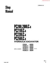
Komatsu PC200LC-6 Shop Manual (711 pages)
Hydraulic Excavator
Brand:
Komatsu
| Category:
Excavators
| Size: 38.61 MB
Table of Contents
Table of Contents
232
Table of Judgment Standard Values
253
Testing and Adjusting
253
Tools for Testing, Adjusting and Troubleshooting
254
Measuringenginespeed
255
Measuring Intake Manifold Pressure
256
Measuring Intake Air Restriction
257
Measuring Lubricating Oil Pressure
258
Measuring Fuel (Filter) Inlet Restriction
259
Measuring Blowby Pressure
260
Measuring Engine Back Pressure
261
Measuringexhaustcolor
262
Measuring Coolant Temperature
263
Measuringvalveclearance
264
Checking and Adjusting Belt Tension for Air Conditioner Compressor
265
Adjustingenginespeedsensor
266
Testing and Adjusting Governor Motor Lever Stroke
267
Testing Clearance of Swing Circle Bearing
268
Testing and Adjusting Track Shoe Tension
269
Testing and Adjusting Hydraulic Pressure in Work Equipment, Swing, Travel Circuit
270
Testing and Adjusting TVC Valve Output Pressure (Servo Piston Input Pressure)
273
Testing and Adjusting LS Valve Output Pressure (Servo Pistion Input Pressure) and LS Differential Pressure
275
Testing and Adjusting Control Pump Circuit Oil Pressure
278
Testing EPC Valve, Solenoid Valve Output Pressure
280
Measuring PPC Valve Output Pressure and Testing PPC Shuttle Valve
282
Adjusting Work Equipment
284
Adjustingtravellever
285
Testing Travel Deviation
286
Testing Location Causing Hydraulic Drift of Work Equipment
287
Measuringoilleakage
289
Releasing Remaining Pressure in Hydraulic Circuit
290
Bleedingair
291
Troubleshooting
293
Points to Remember When Troubleshooting
294
Sequence of Events in Troubleshooting
295
Precautions When Carrying out Maintenance
296
Checks before Troubleshooting
303
Connector Types and Mounting Locations
304
Connector Table for Connector Pin Numbers
308
Explanation of Control Mechanism for Electrical System
321
Display Method and Special Functions of Monitor Panel
322
Method of Using Judgement Table
331
Details of Troubleshooting and Troubleshooting Procedure
335
Troubleshooting of Engine Throttle Controller System (E Mode)
340
Points to Remember When Carring out Troubleshooting of Engine Throttle Controller System
341
Engine Throttle Controller System Circuit Diagram
342
Action Taken by Controller When Abnormality Occurs and Problems on Machine
344
Judgement Table for Engine Throttle Controller and Engine Related Parts
345
Abnormality in Engine Throttle Controller Power Source System
346
(Engine Speed Stays at Low Idling)
346
E3:08] Abnormality in Fuel Control Dial Input Value Is Displayed
347
E3:18] Abnormality (Short Circuit) in Governor Motor Drive System Is Displayed
349
E3:01] Abnormality in Network Reception System Is Displayed
350
E3:05] Abnormality in Model Code Is Displayed
352
E3:06] Abnormality in Governor Potentiometer System Is Displayed
353
E3:07] Abnormality in Pump Controller Throttle System Is Displayed
354
E3:15] Abnormality (Short Circuit) in Battery Relay Output System Is Displayed
354
E3:16] Abnormality (Step-Out) in Governor Motor System Is Displayed
355
E-11 Engine Does Not Start
356
20-I 29
357
A) Idling Speed Is Irregular
358
B)Thereishunting
360
Lack of Output (Engine High Idling Speed Is too Low)
362
E-14 Engine Does Not Stop
364
Defective Operation of Battery Relay System (Engine Does Not Stop)
366
Table of Contents
367
Method of Using Troubleshooting Chart
368
S- 1 Starting Performance Is Poor (Starting Always Takes Time)
372
Enginedoesnotstart
373
Enginedoesnotturn
373
Engine Turns but no Exahaust Gas Comes out (Fuel Is Not Being Injected)
374
Exhaust Gas Comes out but Engine Does Not Start (Fuel Is Being Injected)
375
Engine Does Not Pick up Smoothly (Follow-Up Is Poor)
376
Engine Stops During Operations
377
Engine Does Not Rotate Smoothly
378
Engine Lacks Output (no Power)
379
Exhaust Gas Is Black (Incomplete Combustion)
380
Oil Consumption Is Excessive (or Exhaust Gas Is Blue)
381
Oil Becomes Contaminated Quickly
382
Fuel Consumption Is Excessive
383
S-L 1 Oil Is in Cooling Water, or Water Spurts Back, or Water Level Goes down
384
Oil Pressure Lamp Lights up (Drop in Oil Pressure)
385
S-13 Oil Level Rises
386
Water Temperature Becomes too High (Overheating)
387
S-15 Abnormal Noise Is Made
388
S-16 Vibration Is Excessive
389
Table of Contents
390
Pump Controller System Circuit Diagram
397
Abnormality in Pump Controller Power Source System (Swing Brake Is Not Canceled, Etc)
398
[E2:36] Short Circuit in Rear Pump TVC Solenoid System Is Displayed
399
[E2:37] Disconnection in Rear Pump TVC Solenoid System Is Displayed
401
[E2:06] Short Circuit in Travel Speed Solenoid System Is Displayed
407
[E2:12] Disconnection in LS Select Solenoid System Is Displayed
409
E2:17] Model Selection Input Error Is Displayed
411
E2:18] Network Response Overtime Error Is Displayed
412
[E2:22] Short Circuit in LS Control EPC Solenoid System Is Displayed
414
C-L 1 [E2:23] Disconnection in LS Control EPC Soleniod System Is Displayed
415
[E2:24] Abnormality in Front Pump Pressure Sensor System Is Displayed [E2:25] Abnormality in Rear Pump Pressure Sensor System Is Displayed
416
E2:26] Abnormality in Pump Pressure Sensor Power Source System Is Displayed
418
C-14 [E2:27] Abnormality in Engine Speed Sensor System Is Displayed
419
Table of Contents
433
Logic
436
Pump Merge-Divider
436
Troubleshooting
436
Speeds of All Work Equipment, Swing, Travel Are Slow or Lack Power
437
There Is Excessive Drop in Engine Speed, or Engine Stalls
439
Abnormal Noise Generated (Around Pump)
440
No Work Equipment, Travel, Swing Move
440
Fine Control Ability Is Poor or Response Is Poor
441
Boom Is Slow or Lacks Power
442
Arm Is Slow or Lacks Power
444
Bucket Is Slow or Lacks Power
446
Excessive Hydraulic Drift (Boom, Arm, Bucket)
447
Excessive Time Lag (Engine at Low Idling)
448
H-13 Lack of Power When Pressure Rises
448
Other Equipment Moves When Single Circuit ~S.relieveb
448
H-16 in Compound Operations, Work Equipment with Larger Load Is Slow
449
In L/O, F/O Modes, Work Equipment Speed Is Faster that Specified Speed
449
In Swing + Boom RAISE, Boom RAISE Isslow
450
In Swing + Travel, Travel Speed Drops Excessively
450
Inswing+Armout,Armoutisslow
450
Travel Speed Is Slow
452
H-22 Steering Does Not Turn Easily or Lacks Power
454
H-23 Travel Speed Does Not Switch or Is Faster than Specified Speed
456
Travel Does Not Move (One Side Only)
456
Swing Acceleration Is Poor or Swing Speed Isslow
458
H-27 Excessive Overrun When Stopping Swing
460
Excessive Shock When Stopping Swing (One Direction Only)
461
H-29 Excessive Abnormal Noise When Stopping Swing
461
H-30 Excessive Hydraulic Drift of Swing
462
H-31 Swing Speed Is Faster than Specified Swing Speed
463
Table of Contents
464
None of the Lamps on Monitor Panel Light up
468
Some of the Lamps on Monitor Panel (Gauge Display, Time Display) Do Not Light up
468
When Starting Switch Is Turned ON, Monitor Panel Lamps All Stay Lighted up and Do Not Go out
469
When Starting Switch Is Turned on (Engine Stopped), CHECK Items Flash (Fluid Levels for CHECK Items Are at Specified Level)
470
Coolantlevelflashes
470
Hydraulic Oil Level Flashes
471
M-8 Preheating Is Not Being Used but Preheating Display Lights up
472
When Starting Switch Is Turned on and Engine Is Started, CHECK Items Flash
473
A) Alternator System
473
Engine Oil Pressure Sensor System
475
M-L 0 When Starting Switch Is Turned on (Engine Stopped), CAUTION Items Flash (but When Charge Level, Engine Oil Pressure Do Not Light Up)
475
A) Alternator System
475
Engine Oil Pressure Flashes
476
Coolantlevelflashes
477
Coolant Temperature Flashes
477
Batterychargeflashes
478
Fuellevelflashes
478
No Abnormality Is Displayed on Monitor but Buzzer Sounds
479
When Starting Switch Is Turned on (Engine Stopped), Buzzer Does Not Sound for 1 Second CAUTION Items Are Flashing but Buzzer Does Not Sound
479
Liquid Crystal Night Lighting on Monitor Panel Does Not Light up (Liquid Crystal Display Is Normal)
480
Coolant Temperature Gauge Does Not Rise
481
Coolant Temperature Gauge Does Not Give any Display (None of the Gauge Lamps Light up Duringoperation)
482
Fuel Level Gauge Always Displays FULL
483
Fuel Level Gauge Does Not Give Display
483
Swing Lock Prolix Switch Is on (Prolix), but Monitor Panel Parking Display Does Not Flash
484
Swing Lock Switch Is Turned on (LOCK) but Monitor Panel Parking Display Does Not Light up
484
Defective Fuel Level Sensor System
485
Defective Coolant Temperature Sensor System
486
Defective Engine Oil Level Sensor System
487
Defective Coolant Level Sensor System
488
Defective Hydraulic Oil Sensor System
489
Working Light Does Not Light up
490
Panel Lighting Does Not Light up
490
Light Switch Is Not Being Used but Working Light Lights up
491
A) Wiperdoesnotwork
492
Wiper Switch Is Not Being Used but Wiper Is Actuated
494
Table of Contents
496
Precautions When Carrying out Operation
501
Special Tool List
502
Removal
502
Installation
506
Removal
506
Removal
508
Installation
508
Removal
509
Hydraulic Oil Cooler
510
Installation
511
Removal
511
Removal
515
Fuel Tank
517
Removal
517
Assembly
520
Removal
520
Assembly
524
Pc200-6, Pc2Oolc6, Pc21Olc-6, Pc22Olc-6
524
Assembly
528
Travel Motor
541
Assembly
541
Removal
549
Removal
550
Removal
551
Assembly
559
Removal
560
Swing Circle
562
Removal
562
Recoil Spring
565
Assembly
566
Disassembly
566
Idler
567
Assembly
567
Removal
569
Track Roller
572
Disassembly
572
Removal
574
Carrier Roller
574
Disassembly
574
Assembly
574
Removal
578
Removal
580
Removal
581
Removal
583
Main Pump
590
Disassembly
590
Assembly
607
Removal
607
Removal
608
Control Valve
611
Control Valve Assembly
613
Disassembly
613
Assembly
613
Pressure Compensation Valve
613
Assembly
615
Disassembly
616
Assembly
616
Removal
619
Tvc
619
30-I 25
620
Removal
620
Removal
621
Ls Control Epc Valve
621
Removal
622
Solenoid Valve
622
Removal
623
Swing Ppc Valve
623
Disassembly
627
Travel Ppc Valve
627
Removal
629
Boom Lock Valve
629
Boom Cylinder
630
Removal
631
Arm Cylinder
632
Removal
633
Bucket Cylinder
635
Hydraulic Cylinder
635
Assembly
636
Work Equipment
641
Removal
642
Bucket
644
Installation
646
Removal
646
Table of Contents
658
Final Drive (PC200-6, PC2OOLC-6, PC21 OLC-6, PC220LC-6)
659
Final Drive (PC25OLC-6)
661
Swing Machinery
663
Swingcircle
665
Track Frame, Recoil Spring (PC200-6, PC200LC-6, PC21 OLC-6, PC22OLC-6)
666
Track Frame, Recoil Spring (PC25OLC-6)
667
Idler (PC200-6, PC2OOLC-6, PC21 OLC-6, PC220LC-6)
668
Idler (PC250LC-6)
670
Carrier Roller (PC200-6, PC200LC-6, PC21 OLC-6, PC22OLC-6)
672
Carrier Roller (PC25OLC-6)
673
Track Roller (PC200-6, PC2OOLC-6, PC21 OLC-6, PC220LC-6)
674
Track Roller (PC25OLC-6)
675
Track Shoe (PC200-6, PC2OOLC-6, PC21 OLC-6, PC22OLC-6)
676
Hydraulicpump
680
Controlvalve
682
Safety-Suction Valve for Service Valve
688
Swing Motor
689
Travel Motor (PC200-6, PC200LC-6, PC21 OLC-6, PC22OLC-6)
690
Travel Motor (PC25OLC-6)
691
Work Equipment, Swing PPC Valve
692
Travel Ppcvalve
693
Service PPC Valve
694
PPC Shuttle, Travel Junction Valve
695
Epcsolenoidvalve
697
Center Swivel Joint
698
Boom Holdingvalve
700
Hydraulic Cylinder (PC200-6, PC2OOLC-6, PC21 OLC-6)
701
Hydraulic Cylinder (PC22OLC-6, PC25OLC-6)
703
Workequipment
705
Advertisement
Advertisement
Related Products
Komatsu PC200LC-8M0
Komatsu PC200LC-7
Komatsu PC200LC- 300001
Komatsu PC200LL-8
Komatsu PC200LL-7L
Komatsu PC2000-8 BACKHOE
Komatsu PC2000-8 LOADING SHOVEL
Komatsu PC200-8M0
Komatsu PC200- 300001
Komatsu PC200-7
Komatsu Categories
Excavators
Compact Loader
Trucks
Construction Equipment
Tractor
More Komatsu Manuals
Login
Sign In
OR
Sign in with Facebook
Sign in with Google
Upload manual
Upload from disk
Upload from URL