Sign In
Upload
Manuals
Brands
Motorola Manuals
Radio
CP185 Series
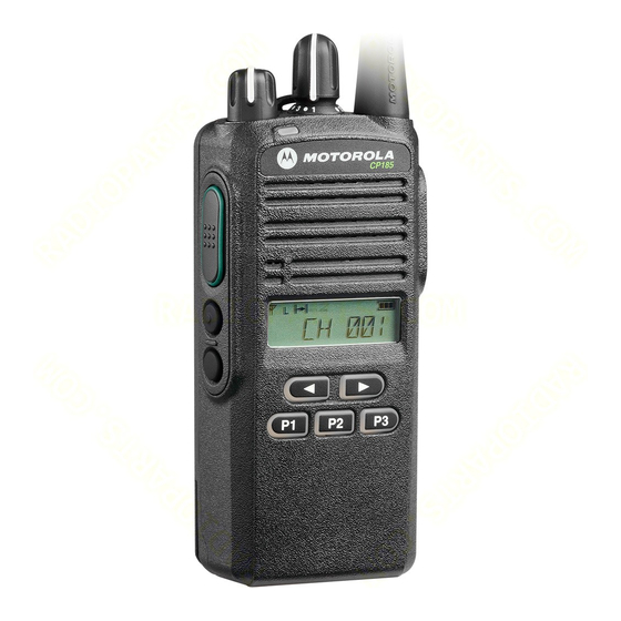
User Manuals: Motorola CP185 Series Two-Way Radio
Manuals and User Guides for Motorola CP185 Series Two-Way Radio. We have
6
Motorola CP185 Series Two-Way Radio manuals available for free PDF download: Basic Service Manual, Quick Reference Manual, User Manual, General Specifications
Motorola CP185 Series Basic Service Manual (120 pages)
Portable radios
Brand:
Motorola
| Category:
Two-Way Radio
| Size: 14.52 MB
Table of Contents
Computer Software Copyrights
5
Product Safety and Rf Exposure Compliance
6
Safety
6
Document History
7
Table of Contents
9
Notations Used in this Manual
15
Chapter 1 Model Charts and Test Specifications
17
Radio Model Information
17
Table 1-1. Radio Model Number (Example:aah03Rdf8Aa7An)
17
Model Chart for UHF2, 435-480 Mhz
18
Model Chart for VHF, 136-174 Mhz
19
UHF2 Specifications
20
VHF Specifications
21
Chapter 2 Theory of Operation
23
Introduction
23
Major Assemblies
23
Receiver
23
Figure 2-1. Receiver Block Diagram
23
RX Front End
24
RX Back End
25
RX Squelch
25
Transmitter
26
Figure 2-2. Transmitter Block Diagram
26
Phase Lock Loop Synthesizer
27
Figure 2-3. PLL Synthesizer Block Diagram
27
RX Audio Circuit
28
Figure 2-4. RX Audio Block Diagram
28
TX Audio Circuit
29
Figure 2-5. TX Audio Block Diagram (UHF1 and UHF2)
29
Figure 2-6. TX Audio Block Diagram (VHF)
29
Microcontroller
30
Power Supply
31
Chapter 3 Test Equipment, Service Aids, and Service Tools
33
Test Equipment
33
Table 3-1. Recommended Test Equipment
33
Service Aids
34
Table 3-2. Service Aids
34
Figure 3-1. Programming/Test Cable (PMDN4077_R)
35
Figure 3-2. Cloning Cable (PMDN4076_R)
35
Figure 3-3. Wiring of the Connectors
35
Chapter 4 Performance Checks
37
General
37
Power-Up Self Test
37
Lcd/Led/Button/Volume Knob Test Mode
37
Figure 4-1. LCD Indication
37
Table 4-1. Radio Operation in Test Mode
38
Led/Button/Volume Knob Test Mode (Non Keypad Models)
39
Table 4-2. Radio Operation in Test Mode - Non Keypad Models
39
Chapter 5 Radio Programming and Tuning
41
Introduction
41
CPS Programming Setup
41
Radio-To-Radio Cloning
41
Figure 5-1. CPS Programming Setup
41
Radio Tuning Setup
42
Initial Test Equipment Control Settings
43
Figure 5-2. Radio Tuning Setup
43
Table 5-1. Initial Equipment Control Settings
43
Transmitter Alignment Options
44
Table 5-2. Transmit High/Low Power Level
44
Figure 5-3. Tx High Power Window (High Power)
45
Transmit High Power Tuning
45
Transmit Low Power Tuning
45
Transmit Modulation Tuning
46
Service Monitor Setting
46
Figure 5-4. Tx Low Power Window (Low Power)
46
Table 5-3. Transmit Modulation Tuning
46
Transmit 12.5 Khz Modulation Tuning
48
Figure 5-5. Tx Modulation 12.5 Khz Window
48
Transmit 25 Khz Modulation Tuning
49
Figure 5-6. Tx Modulation 25 Khz Window
49
Transmit MDC Signaling System Modulation Tuning
50
Service Monitor Setting
50
Table 5-4. Transmit MDC Signaling System Modulation Tuning
50
Transmit MDC Signaling System 12.5 Khz Modulation Tuning
51
Figure 5-7. Tx MDC Signaling System Modulation 12.5 Khz Window
51
Transmit MDC Signaling System 25 Khz Modulation Tuning
52
Receiver Tuning
52
Service Monitor Setting
52
Figure 5-8. Tx MDC Signaling System Modulation 25 Khz Window
52
Table 5-5. Receiver Squelch Tuning
52
Receive 12.5 Khz-Band Normal Squelch Tuning
54
Receive 12.5 Khz-Band Tight Squelch Tuning
54
Figure 5-9. Rx 12.5 Khz-Band Normal Squelch Tuning Window
54
Receive 25 Khz-Band Normal Squelch Tuning
55
Figure 5-10. Rx 12.5 Khz-Band Tight Squelch Tuning Window
55
Receive 25 Khz-Band Tight Squelch Tuning
56
Figure 5-11. Rx 25 Khz-Band Normal Squelch Tuning Window
56
Utilities
57
Program Serial no
57
Figure 5-12. Rx 25 Khz-Band Tight Squelch Tuning Window
57
Figure 5-13. Program Radio Serial No. Window
57
Front Panel Feature and Button Configuration Mode (Keypad Models Only)
58
Introduction
58
Entering Programming Mode
58
Exiting Programming Mode
58
Accessing Front Panel Programming Mode Parameters
58
Editing Front Panel Programming Mode Parameters
59
Table 5-6. Front Panel Programming Mode Parameters: Non-MDC1200 & Non-QCII Models
59
Table 5-7. Front Panel Programming Mode Parameters: MDC1200 & QCII Models
61
Chapter 6 Maintenance - CP185
65
Introduction
65
Preventive Maintenance
65
Inspection
65
Cleaning Procedures
65
Safe Handling of CMOS and LDMOS Devices
66
Disassembling and Reassembling the Radio - General
67
Figure 6-1. Limited Keypad with Channel Knob Model
67
Radio Disassembly - Detailed
68
Front Housing from Chassis Disassembly
68
Figure 6-2. Battery and Antenna Removal
68
Figure 6-3. Knobs Removal
69
Figure 6-4. Chassis Removal
69
Figure 6-5. Speaker Wire and Flexible Cable Connection
70
Figure 6-6. Speaker Wire Removal
70
Chassis Assembly Disassembly
71
Figure 6-7. Unlatch the Flexible Cable
71
Figure 6-8. Sub-Circuit Board and Accessory Bracket Removal
71
Front Circuit Board, Display Module and Keypad Disassembly
72
Figure 6-9. Main Circuit Board, O-Ring and Battery Contact Seal Removal
72
Figure 6-10. Front Circuit Board Removal
72
Speaker Disassembly
73
Figure 6-11. LCD and Keypad Removal
73
Figure 6-12. Speaker Removal
74
Radio Reassembly - Detailed
75
Speaker Reassembly
75
Front Circuit Board, Display Module and Keypad Reassembly
75
Figure 6-13. Speaker Reassembly
75
Figure 6-14. LCD and Keypad Reassembly
75
Chassis Assembly Reassembly
76
Figure 6-15. Front Circuit Board Reassembly
76
Figure 6-16. Main Circuit Board, O-Ring and Battery Contact Seal Reassembly
77
Figure 6-17. Sub Circuit Board and Accessory Bracket Reassembly
77
Chassis and Front Housing Reassembly
78
Torque List
78
Figure 6-18. Chassis Assembly and Front Housing Assembly Reassembly
78
Table 6-1. Torque Chart
78
Mechanical View and Parts List
79
CP185 View and Parts List
79
Figure 6-19. CP185 Exploded View
79
Figure 6-20. "20" Marking on Front Housing
81
Chapter 7 Maintenance - CP185
83
Introduction
83
Preventive Maintenance
83
Inspection
83
Cleaning Procedures
83
Safe Handling of CMOS and LDMOS Devices
84
Repair Procedures and Techniques - General
85
Table 7-1. Lead Free Solder Wire Part Number List
85
Table 7-2. Lead Free Solder Paste Part Number List
85
Disassembling and Reassembling the Radio
88
Figure 7-1. Non Keypad with Channel Knob Model
88
Radio Disassembly - Detailed
89
Front Housing from Chassis Disassembly
89
Figure 7-2. Battery and Antenna Removal
89
Figure 7-3. Knobs Removal
90
Figure 7-4. Chassis Removal
90
Figure 7-5. Speaker Wire and Flexible Cable Connection
91
Figure 7-6. Speaker Wire Removal
91
Chassis Assembly Disassembly
92
Figure 7-7. Unlatch the Flexible Cable
92
Figure 7-8. Sub-Circuit Board and Accessory Bracket Removal
92
Figure 7-9. Main Circuit Board, Finger Strips, O-Ring and Battery Contact Seal Removal (UHF1)
93
Figure 7-10. Main Circuit Board, Finger Strips, O-Ring and Battery Contact Seal Removal (UHF2)
93
Front Circuit Board and Poron Pad Disassembly
94
Speaker Disassembly
94
Figure 7-11. Front Circuit Board Removal
94
Figure 7-12. Poron Pad Removal
94
Radio Reassembly - Detailed
95
Speaker Reassembly
95
Figure 7-13. Speaker Removal
95
Figure 7-14. Speaker Reassembly
95
Front Circuit Board and Poron Pad Reassembly
96
Figure 7-15. Poron Pod Reassembly
96
Figure 7-16. Front Circuit Board Reassembly
96
Chassis Assembly Reassembly
97
Figure 7-17. Main Circuit Board, Finger Strips, O-Ring and Battery Contact Seal Reassembly
97
Figure 7-19. Sub Circuit Board and Accessory Bracket Reassembly
98
Figure 7-18. Main Circuit Board, Finger Strips, O-Ring and Battery Contact Seal Reassembly
98
Chassis and Front Housing Reassembly
99
Torque List
99
Figure 7-20. Chassis Assembly and Front Housing Assembly Reassembly
99
Table 7-3. Torque Chart
99
Mechanical View and Parts List
100
CP185 (Non Keypad with Channel Knob) Exploded View and Parts List
100
Figure 7-21. CP185 (Non Keypad) Radio Exploded View
100
Table 7-4. Parts List (Non Keypad with Channel Knob)
101
Figure 7-22. "20" Marking on Front Housing
102
Chapter 8 Troubleshooting Tables
105
Error Codes
105
Table 8-1. Error Code Display
105
Troubleshooting Table for Receiver
106
Table 8-2. Receiver Troubleshooting Table
106
Troubleshooting Table for Transmitter
107
Table 8-3. Transmitter Troubleshooting Table
107
Appendix A Accessories
109
Belt Clip
110
Carrying Accessories
110
Appendix B Warranty, Service Support, and Replacement Parts
111
Scope of Manual
111
Warranty
111
Warranty Period and Return Instructions
111
After Warranty Period
111
Piece Parts
111
B.1 Scope of Manual
111
Appendix C Repair Procedures and Techniques - General
113
Table C-1. Lead Free Solder Wire Part Number List
113
Table C-2. Lead Free Solder Paste Part Number List
113
Rigid Circuit Boards
114
Glossary of Terms
117
Advertisement
Motorola CP185 Series Basic Service Manual (84 pages)
Brand:
Motorola
| Category:
Portable Radio
| Size: 5.56 MB
Table of Contents
Computer Software Copyrights
5
Safety
6
Document History
7
Table of Contents
9
Notations Used in this Manual
15
Chapter 1 Model Charts and Test Specifications
17
Radio Model Information
17
Table 1-1. Radio Model Number (Example:aah03Rdf8Aa7An)
17
Model Chart for UHF2, 435-480 Mhz
18
Model Chart for VHF, 136-174 Mhz
19
UHF2 Specifications
20
VHF Specifications
21
Chapter 2 Theory of Operation
23
Introduction
23
Major Assemblies
23
Receiver
23
Figure 2-1. Receiver Block Diagram
23
RX Back End
24
RX Front End
24
RX Squelch
25
Transmitter
25
Figure 2-2. Transmitter Block Diagram
25
Phase Lock Loop Synthesizer
26
Figure 2-3. PLL Synthesizer Block Diagram
26
RX Audio Circuit
27
Figure 2-4. RX Audio Block Diagram
27
TX Audio Circuit
28
Figure 2-5. TX Audio Block Diagram
28
Microcontroller
29
Power Supply
29
Chapter 3 Test Equipment, Service Aids, and Service Tools
31
Test Equipment
31
Table 3-1. Recommended Test Equipment
31
Service Aids
32
Table 3-2. Service Aids
32
Figure 3-1. Programming/Test Cable (PMDN4077_R)
33
Figure 3-2. Cloning Cable (PMDN4076_R)
33
Figure 3-3. Wiring of the Connectors
33
Chapter 4 Performance Checks
35
General
35
Power-Up Self Test
35
Lcd/Led/Button/Volume Knob Test Mode
35
Figure 4-1. LCD Indication
35
Table 4-1. Radio Operation in Test Mode
35
Chapter 5 Radio Programming and Tuning
37
Introduction
37
Radio-To-Radio Cloning
37
CPS Programming Setup
37
Figure 5-1. CPS Programming Setup
37
Radio Tuning Setup
38
Figure 5-2. Radio Tuning Setup
38
Initial Test Equipment Control Settings
39
Transmitter Alignment Options
39
Table 5-1. Initial Equipment Control Settings
39
Table 5-2. Transmit High/Low Power Level
39
Figure 5-3. Tx High Power Window (High Power)
40
Transmit High Power Tuning
40
Figure 5-4. Tx Low Power Window (Low Power)
41
Transmit Low Power Tuning
41
Transmit Modulation Tuning
42
Transmit 12.5 Khz Modulation Tuning
42
Figure 5-5. Tx Modulation 12.5 Khz Window
42
Table 5-3. Transmit Modulation Tuning
42
Transmit 25 Khz Modulation Tuning
43
Figure 5-6. Tx Modulation 25 Khz Window
43
Receiver Tuning
44
Receive 12.5 Khz-Band Normal Squelch Tuning
44
Figure 5-7. Rx 12.5 Khz-Band Normal Squelch Tuning Window
44
Table 5-4. Receiver Squelch Tuning
44
Receive 12.5 Khz-Band Tight Squelch Tuning
45
Figure 5-8. Rx 12.5 Khz-Band Tight Squelch Tuning Window
45
Receive 25 Khz-Band Normal Squelch Tuning
46
Figure 5-9. Rx 25 Khz-Band Normal Squelch Tuning Window
46
Receive 25 Khz-Band Tight Squelch Tuning
47
Figure 5-10. Rx 25 Khz-Band Tight Squelch Tuning Window
47
Utilities
48
Program Serial no
48
Front Panel Feature and Button Configuration Mode
48
Introduction
48
Entering Programming Mode
48
Exiting Programming Mode
48
Accessing Front Panel Programming Mode Parameters
48
Figure 5-11. Program Radio Serial No. Window
48
Editing Front Panel Programming Mode Parameters
49
Table 5-5. Front Panel Programming Mode Parameters
49
Chapter 6 Maintenance - CP185
51
Introduction
51
Preventive Maintenance
51
Inspection
51
Cleaning Procedures
51
Safe Handling of CMOS and LDMOS Devices
52
Disassembling and Reassembling the Radio - General
53
Figure 6-1. Limited Keypad with Channel Knob Model
53
Radio Disassembly - Detailed
54
Front Housing from Chassis Disassembly
54
Figure 6-2. Battery and Antenna Removal
54
Figure 6-3. Knobs Removal
55
Figure 6-4. Chassis Removal
55
Figure 6-5. Speaker Wire and Flexible Cable Connection
56
Figure 6-6. Speaker Wire Removal
56
Chassis Assembly Disassembly
57
Figure 6-7. Unlatch the Flexible Cable
57
Figure 6-8. Sub-Circuit Board and Accessory Bracket Removal
57
Front Circuit Board, Display Module and Keypad Disassembly
58
Figure 6-9. Main Circuit Board, O-Ring and Battery Contact Seal Removal
58
Figure 6-10. Front Circuit Board Removal
58
Speaker Disassembly
59
Figure 6-11. LCD and Keypad Removal
59
Figure 6-12. Speaker Removal
60
Radio Reassembly - Detailed
61
Speaker Reassembly
61
Front Circuit Board, Display Module and Keypad Reassembly
61
Figure 6-13. Speaker Reassembly
61
Figure 6-14. LCD and Keypad Reassembly
61
Chassis Assembly Reassembly
62
Figure 6-15. Front Circuit Board Reassembly
62
Figure 6-16. Main Circuit Board, O-Ring and Battery Contact Seal Reassembly
63
Figure 6-17. Sub Circuit Board and Accessory Bracket Reassembly
63
Chassis and Front Housing Reassembly
64
Torque List
64
Figure 6-18. Chassis Assembly and Front Housing Assembly Reassembly
64
Table 6-1. Torque Chart
64
Mechanical View and Parts List
65
CP185 View and Parts List
65
Figure 6-19. CP185 Exploded View
65
Chapter 7 Troubleshooting Tables
69
Error Codes
69
Table 7-1. Error Code Display
69
Troubleshooting Table for Receiver
70
Table 7-2. Receiver Troubleshooting Table
70
Troubleshooting Table for Transmitter
71
Table 7-3. Transmitter Troubleshooting Table
71
Appendix A Accessories
73
Audio Accessories
73
Belt Clip
74
Appendix B Warranty, Service Support, and Replacement Parts
75
Scope of Manual
75
Warranty
75
Warranty Period and Return Instructions
75
After Warranty Period
75
Piece Parts
76
Appendix C Repair Procedures and Techniques - General
77
Table C-1. Lead Free Solder Wire Part Number List
77
Table C-2. Lead Free Solder Paste Part Number List
77
Glossary of Terms
81
Motorola CP185 Series Quick Reference Manual (86 pages)
Brand:
Motorola
| Category:
Two-Way Radio
| Size: 4.46 MB
Table of Contents
Radio Overview
4
Menu Navigation Buttons
8
Programmable Buttons
8
LCD Display Icons
11
Attaching/Removing the Antenna
15
Attaching/Removing the Battery
16
Attaching/Removing the Belt Clip
17
Charging the Battery
18
Receiving Transmission
19
Transmitting a Message
19
Nuisance Channel Delete
21
Voice Operated Transmit VOX
22
Voice Inversion Scrambling
23
Intrinsically Safe Radio Information
33
Motorola Limited Warranty for the United States and Canada
37
Products and Accessories
37
What Does this Warranty Cover
37
What Other Limitations Are There
40
How to Obtain Warranty Service or Other Information
40
Commandes de la Radio
44
CP185 Radio Sans Clavier
46
Touches de Navigation de Menus
48
Touches Programmables
48
Fixation/Retrait de L'antenne
54
Installation/Retrait de Batterie
55
Recharge de la Batterie
57
Réception de la Transmission
58
Transmission D'un Message
58
Suppression de Canal Importun
60
Transmission À la Voix VOX
61
Brouillage Par Inversion de Voix
62
Brochure Normes de Sécurité Et Exposition À L'énergie de RF Pour L'utilisation des Radios Bidirectionnelles Portatives
63
Interférence Et Compatibilité Électromagnétique
70
Garantie Limitée de Motorola Pour Les États-Unis Et Le Canada
78
Qui Est Couvert
80
Advertisement
Motorola CP185 Series User Manual (42 pages)
Brand:
Motorola
| Category:
Two-Way Radio
| Size: 1.63 MB
Table of Contents
Table of Contents
3
Computer Software Copyrights
4
Safety
5
Radio Overview
7
Led Indicator
8
Accessory Connector
8
LED Colors
9
LCD Display and Icons
10
Programmable Buttons
11
Getting Started
13
Attaching and Removing the Antenna
13
Attaching and Removing the Battery
14
Attaching and Removing the Belt Clip
15
Charging the Battery
16
Scan
18
Deleting a Nuisance Scan Channel
18
Voice Operated Transmit (VOX)
19
Voice Inversion Scrambling
20
Front Panel Programming Mode
21
Entering Front Panel Programming
21
Mode
21
Exiting Front Panel Programming Mode
21
Assessing Front Panel Programming Mode Parameters
21
Main Menu
23
TPL and DPL Frequencies and Codes
27
TPL Frequency
27
DPL Codes
29
Motorola Limited Warranty for the United
32
States and Canada
32
Products and Accessories
32
Accessories
37
Motorola CP185 Series User Manual (40 pages)
Brand:
Motorola
| Category:
Radio
| Size: 1.9 MB
Table of Contents
Table of Contents
3
Computer Software Copyrights
4
Safety
5
Radio Overview
7
LED Colors
9
LCD Display and Icons
10
Programmable Buttons
11
Getting Started
13
Attaching and Removing the Antenna
13
Attaching and Removing the Battery
14
Attaching and Removing the Belt Clip
15
Charging the Battery
16
Scan
18
Deleting a Nuisance Scan Channel
18
Voice Operated Transmit (VOX)
19
Voice Inversion Scrambling
20
Front Panel Feature and Button Configuration Mode
21
Entering Front Panel Feature and Button Configuration Mode
21
Exiting Front Panel Feature and Button Configuration Mode
21
Assessing Front Panel Feature and Button Configuration Mode Parameters
21
TPL and DPL Frequencies and Codes
26
TPL Frequency
26
DPL Codes
28
Warranty
31
Accessories
35
Motorola CP185 Series General Specifications (2 pages)
Brand:
Motorola
| Category:
Receiver
| Size: 0.23 MB
Advertisement
Related Products
Motorola CM360
Motorola Spectra SmartNet C2
Motorola Spectra SmartNet C4
Motorola Spectra SmartNet C5
Motorola Spectra SmartNet C7
Motorola CDM750
Motorola Canopy AP
Motorola Commercial CM Series
Motorola Commercial CM306
Motorola CM30
Motorola Categories
Cell Phone
Two-Way Radio
Baby Monitor
Cordless Telephone
Radio
More Motorola Manuals
Login
Sign In
OR
Sign in with Facebook
Sign in with Google
Upload manual
Upload from disk
Upload from URL