Sign In
Upload
Manuals
Brands
NEC Manuals
Telephone
NEAX 2400 IPX
NEC NEAX 2400 IPX Manuals
Manuals and User Guides for NEC NEAX 2400 IPX. We have
7
NEC NEAX 2400 IPX manuals available for free PDF download: Programming Manual, User Manual, Manual, Reference Manual
NEC NEAX 2400 IPX Manual (197 pages)
Fusion Network
Brand:
NEC
| Category:
Network Hardware
| Size: 9.24 MB
Table of Contents
Table of Contents
6
List of Figures
10
Chapter 1 Introduction
16
General
16
How to Follow this Manual
16
Related Manuals
17
Chapter 2 General
18
What Is Fusion and Its Advantages
18
Improved Inter-Office Service Features
18
Use of Telephone Numbers
18
Free Numbering
19
Centralized Maintenance Administration Terminal (MAT)
19
Figure 2-2 Free Location
19
Figure 2-3 Centralized MAT on Fusion Network
19
Fusion System Configuration
20
Figure 2-4 Fusion System Configuration (with FCH)
20
Figure 2-5 Fusion System Configuration (Without FCH)
20
Node
21
Figure 2-6 Maximum System Configuration
21
Data Memory Configuration
22
Figure 2-7 Network Data Memory
22
Fusion Network Examples
23
Figure 2-8 Network Data Memory Copy
23
Figure 2-9 Closed Numbering Fusion-CCIS Network
23
Figure 2-1 Telephone Number
24
Figure 2-10 Open Numbering Fusion-CCIS Network
24
Table 2-1 Available Telephone Number Digits
24
Tandem Connections Via Fusion Link
25
Figure 2-11 Tandem Connections Via Fusion Link
25
Chapter 3 System Configuration
26
FUSION System Without FCH
26
Figure 3-1 FUSION System Configuration Without FCH
26
Fusion System with FCH
27
System Configuration
27
Figure 3-2 Fusion System Configuration with FCH
27
Redundancy of FUSION Link
28
Figure 3-3 Add a Direct Connection to Fusion System with FCH
28
Figure 3-4 Redundant Configuration (LANI, HUB, FCH, and DTI)
29
Figure 3-5 Redundant Configuration (HUB, FCH, and DTI)
29
Figure 3-6 Redundant Configuration (FCH and DTI)
29
Figure 3-7 Non-Redundant Configuration
30
Figure 3-8 Unavailable System Configurations
30
System Considerations
31
Fusion Network Conditions
31
Figure 3-9 Fusion Network Topologies
31
Figure 3-10 Fusion Tandem Connections
32
Figure 3-11 Maximum Number of Ports between Nodes
32
Figure 3-12 Connection Trunk Alternate Routing
33
Figure 3-13 Fusion Network on an Associated Basis
33
Centralized Billing - Fusion (Polling Method)
35
Figure 3-14 Centralized Billing - Fusion (1/3)
35
Centralized Management Report-Fusion
38
Figure 3-15 Centralized Management Report-Fusion
38
Figure 3-16 Centralized Management Report-Fusion (Example 1)
39
Figure 3-17 Centralized Management Report-Fusion (Example 2)
40
Figure 3-18
41
Fusion Attendant/Desk Console
42
Operator Call
42
Figure 3-19 Operator Calls on a Fusion Network
42
Central Office Incoming Call (Ring Down)
43
Figure 3-20 Ring down Calls on a Fusion Network
43
Day/Night Change
44
Figure 3-21 Day/Night Information Transfer by ATTCON/DESKCON
44
Figure 3-22 Day/Night Information Transfer
44
Installation
46
Anti-Static Caution
46
Figure 4-1 Static Caution Indicator
46
Figure 4-2 How to Use the Anti-Static Kit
47
Circuit Cards Required
48
Figure 4-3 Circuit Cards for Fusion
48
Key Setting on Circuit Cards
49
Pa-M96 (Hub)
49
Figure 4-4 Switch Setting on HUB (PA-M96) Card
49
Table 4-1 SENSE Switch Setting
49
Pa-Fcha (Fch)
50
Figure 4-5 Switch Setting on FCH (PA-FCHA) Card
50
Table 4-2 MODE Switch Setting
51
Table 4-3 DIP Switch (SW14) Setting
51
Pa-24Dtr (Dti)
52
Figure 4-6 Switch Locations on DTI (PA-24DTR) Card
52
Table 4-4 Switch Setting Patterns for the DTI Card
52
Digital PAD Setting
56
Table 4-5 Digital Pad Setting
56
Mounting Circuit Cards in PIM
57
Mounting HUB (PA-M96) in a PIM
57
Figure 4-7 Mounting HUB Card in PIM 0
57
Mounting FCH (PA-FCHA) and DTI (PA-24DTR) Cards
58
Figure 4-8 Mounting FCH and DTI Cards
58
Connecting Cables
59
Connecting DTI-FCH Front Cables
59
Figure 4-9 Connecting Front Cables
59
Figure 4-10 FCH Cascade Connections
60
Connecting 10 BASE-T Cables
61
Figure 4-11 Overall 10 BASE-T Connections
61
BASE-T Connection Procedure
62
Procedure for 1-IMG System
62
When Using Cable Unit SR1201 ETIF CAU-N
62
When Not Using the Cable Unit SR1201 ETIF CAU-N
63
Procedure for 4-IMG System
63
Procedure for IPX-U and IMX-U Systems
64
Figure 4-12 Connecting 10 BASE-T Cables (Example)
65
Figure 4-13 Examples of Ethernet Cable Connection-FCH in PIM0 (1-IMG System) (1/2
66
Table 4-6 Connection of 10 BASE-T Cables to FCH Card(S) in PIM0 of 1-IMG
66
Figure 4-14 Examples of Ethernet Cable Connection-FCH in PIM1 (1-IMG System)
68
Table 4-7 Connection of 10 BASE-T Cables to FCH Card(S) in PIM1 of 1-IMG
68
Figure 4-15 Examples of Ethernet Cable Connection-FCH in PIM2 (1-IMG System) (1/2)
69
Table 4-8 Connection of 10 BASE-T Cables to FCH Card(S) in PIM2 of 1-IMG
69
Figure 4-16 Examples of Ethernet Cable Connection-FCH in PIM3 (1-IMG System) (1/2)
71
Table 4-9 Connection of 10 BASE-T Cables to FCH Card(S) in PIM3 of 1-IMG
71
Chapter 5 Data Programming
74
Figure 5-1 Data Programming Flow Chart
74
Network Data Programming Summary
75
Brand-New Fusion Network
75
System Data
75
Numbering Plan Data
75
Station Numbering
75
Fusion Link Data
76
Upgrading a CCIS Network
76
System Data
76
Numbering Plan Data
76
Station Numbering
76
Fusion Link Data
77
Figure 5-2 Fusion-CCIS Network
77
Figure 5-3 How to Upgrade the Numbering Plan Data of an Existing CCIS Network
78
Assignment of System Data
79
Figure 5-4 Assignment of Memory Block
79
Figure 5-5 LDM and NDM Allocation (ASYDL)
79
Figure 5-6 Self-FPC Assignment
80
Figure 5-7 DP Signal Relay Broadcasting over Fusion Link (Example)
80
Figure 5-8 ASYDN Command Display (Example)
82
Assignment of FPC and MG and UNIT into Network
83
Afmu
83
Figure 5-9 Assignment of Module Accommodation Data
83
Figure 5-10 AFMU Command Display
83
Assignment of Logical RT in Network DM (NDM)
84
Alrtn/Artkn
84
Figure 5-11 Telephone Number Required
84
Figure 5-12 Assignment of Logical Route Number
84
Assignment of Numbering Data for Telephone Numbers
85
Figure 5-13 ALRTN Command Display
85
Figure 5-14 Telephone Number Allocation
85
Figure 5-15 ANPDN Sample Data Sheet
86
Figure 5-16 ANPDN Command Display
86
Figure 5-17 ASPAN Sample Data Sheet
87
Figure 5-18 ASPAN Command Display
87
Assignment of Telephone Numbers
88
Figure 5-19 ALGSN Data Sheet (Example)
88
Figure 5-20 ALGSN Command Display (Example)
89
Assignment of Connection Route/Trunk Data
90
Figure 5-21 B-Ch and D-Ch (Example)
90
Figure 5-22 ACRD Command Display (Example)
90
Table 5-1 Route Class Data Assignment
91
When FCH Is Mounted in a Extended Density Slot
94
Figure 5-23 ACTK Command Display (Example)
94
Figure 5-24 Mounting FCH and DTI Cards in Regular Density Slots
94
Table 5-2 Data Programming Sheet for Regular Density Slot
95
When FCH Is Mounted in a High Density Slot
96
Figure 5-25 Mounting FCH and DTI Cards in High-Density Slots
96
Figure 5-26 How to Assign C_LEN Data (Type 2)
97
Table 5-3 Data Programming Sheet for High Density Slot
98
Assignment of FCH Related Data
99
Figure 5-27 MBCT Command Display
99
Figure 5-28 Assignment of FCH Number
100
Figure 5-29 AFCH Command Display (Example)
100
Figure 5-30 AFRT Sample Data Sheet
101
Figure 5-31 AFRT Command Display
101
Figure 5-32
102
Figure 5-33 AFPC Command Display (Example)
102
Figure 5-34 AFPC Sample Data Sheet
103
Figure 5-35 AFPC/AETH Sample Data Assignment
104
Assignment of Access Code for Tandem Connection Via FCCS - ACIS
105
Figure 5-36 ACAN Sample Data Sheet
105
Figure 5-37 ACAN Command Display (Example)
105
Ogc
106
Figure 5-38 Assignment of Routing Data Using LDM
106
Figure 5-39 Example of OGC
106
Ogca
107
Figure 5-40 Example of OGCA
108
Lcr/Lcrs
109
Figure 5-41 Example of LCR/LCRS
109
Data Assignment for 52M-SDH Interface
112
Figure 5-42 Fusion Connection with 52M-SDH Interface
112
Data Programming
113
Figure 5-43 Assignment of Different Route Numbers for FCCS and CCIS Links (Example)
113
Flexible Routing - Fusion
115
Network Data Programming for Tandem Connection Via "FCCS" - "CCIS
115
Figure 5-44 FCCS - CCIS Coexisting Network
116
FCCS Link Via Internet/Intranet
118
External Router
118
Figure 5-45 External Router - Overview
119
Figure 5-46 Hardware Connections for External Router
119
Figure 5-47 Switch Setting on FCH/FGH (PA-FCHA) Card
120
Figure 5-48 Connection Route Class Data Sample
121
Figure 5-49 Sample Data Assignment (ACTK)
122
Figure 5-50 Sample Data Assignment (AFCD)
123
Figure 5-51 Assignment of FCHN (Example)
124
Figure 5-52 Sample Data Assignment (AFPC)
125
Figure 5-53 Internal LAN Routing Data Assignment Image (Example)
125
Figure 5-53 Figure 5-52 Sample Data Assignment (AETH)
126
Figure 5-54 How to Assign Destination IP and Next IP
126
Fusion over IP
127
Figure 5-55 Sample Data Assignment (ACAN)
127
Figure 5-56 Fusion over IP - Overview
128
Figure 5-57 Hardware Connections for Fusion over IP
128
Figure 5-58
129
Figure 5-59
129
Figure 5-60
130
Figure 5-61
131
Figure 5-62
131
Figure 5-63
132
Figure 5-64
132
Figure 5-65
133
Figure 5-66 "Basic LENS Data" Assignment of Speech Channels (AFIP)
134
Office Data Sheets
136
Data Sheet for AFMUPL
136
Data Sheet for ALRTN
137
Data Sheet for ANPD/ANPDL/ANDPN
138
Data Sheet for ASPA/ASPAL
139
Data Sheet for ALGNL
140
Data Sheet for ALGSL (TYPE1)
141
Data Sheet for ALGSL (TYPE2)
142
Data Sheet for ASDT
143
Data Sheet for ACRD
144
Data Sheet for ACTK
146
Data Sheet for AFCH
147
Data Sheet for AFPC
149
Data Sheet for ACAN
151
Data Sheet for AFRT
152
Data Sheet for AFRFL
153
Data Sheet for AETH
154
Data Sheet for AGIP
155
Data Sheet for AFIP
158
Chapter 6 Post Installation Test
160
How to Check Fusion Link by Leds on FCH Card
160
Figure 6-1 Fusion Network
160
How to Check LYR LED
161
Repair Procedure When LED Indicates Abnormality
161
Figure 6-2 LED Indications on Fusion Link Related Circuit Cards
161
Front Cable
162
How to Perform the Fusion Link Test
162
Fusion Link Test Mode Setting
162
Figure 6-3 Fusion Link Test Mode
162
Loopback Point Designation
163
Test Procedure
163
Figure 6-4 Loopback Points of DTI Card
163
Figure 6-5 How to Set the Fusion Link Test Mode
164
Figure 6-6 Loopback Point Designation
164
FCCS Network Connection Test
165
Station-To-Station Connection Test (Via FCCS)
165
FCCS Call Origination Test
165
Figure 6-7 Fusion Link-Test Results
165
FCCS Call Termination Test
166
ATTCON Connection Test (Via FCCS)
166
Figure 6-8 Station-To-Station Connection Test (Origination) Via FCCS
166
ATTCON Call Origination Test
167
ATTCON Call Termination Test
167
Line (LC, ELC, DLC Card) Connection Test (Via FCCS)
167
Figure 6-9 ATTCON Connection Test (Origination) Via FCCS
167
Line Origination Test: Confirmation of Physical/Telephone STN Number
168
Line Termination Test: Confirmation of Telephone STN Number
168
Line Connection Test: Case of Hot Line/House Phone Involved
168
3-Party Conference Trunk Function Test (Via FCCS)
168
Figure 6-10 Line Connection Test (Origination) Via FCCS
168
FCCS Alternate Routing Test
169
Primary Route Trunk Test
169
Figure 6-11 3-Party Conference Trunk Function Test Via FCCS
169
Alternate Route Trunk Test
170
Fusion and Non-Fusion Connection Tests
170
When Seizing a Trunk from a Station
170
Figure 6-12 FCCS Alternate Routing Test
170
When Seizing a Trunk from an ATTCON
171
Figure 6-13 CCIS-FCCS Outgoing Call Test
171
SDT Card Loopback Test
172
Figure 6-14 Loopback Points of SDT Card
172
Figure 6-15 Loopback Setting by P-SW Key on PA-SDTA Card
172
Chapter 7 Troubleshooting
174
List of Fusion-Related System Messages
174
Table 7-1 List of Fusion-Related System Messages
174
B PM C-Level Infinite Loop (Permanent)
175
Figure 7-1 Related Hardware
175
Figure 7-2 3-B PM C-Level Infinite Loop (Permanent)
175
Repair Procedure
176
Figure 7-3 How to Initialize the FCH (PA-FCHA) Card
176
Figure 7-4 How to Replace the FCH (PA-FCHA) Card
177
C PM C-Level Infinite Loop (Temporary)
178
Repair Procedure
178
D PM Lockup Failure (Permanent)
178
Figure 7-5 3-C PM C-Level Infinite Loop (Temporary)
178
Figure 7-6 3-D PM Lockup Failure (Permanent)
178
Repair Procedure
179
E PM Lockup Failure (Temporary)
179
Figure 7-7 3-E PM Lockup Failure (Temporary)
179
H/I/J Signaling Link Failure (Permanent)/(Temporary)/(Recovery)
180
Figure 7-8 13-H/13-I/13-J Signaling Link Failure System Message
180
Figure 7-9 Fusion Link (Signaling Link) Failure
180
Repair Procedure
181
Figure 7-10 FCH-DTI Connection
181
S FCH Failure Notification (Detection)
182
Figure 7-11 23-S FCH Failure Notification
183
Repair Procedure
185
Figure 7-12 10 BASE-T Cable Connection Check
185
Figure 7-13 How to Check 10 BASE-T Cables
185
Figure 7-14 How to Replace HUB (PA-M96) Card
187
T FCH Fault Notification (Recovery)
188
Figure 7-15 23-T FCCH Fault Recovery Notification
188
U FCH Status Information
189
FLTINF = 00H Initial Setting Failure
190
Figure 7-16 23-U FCCH Status Information
190
FLTINF = 18H Spanning Tree Abnormal Answer
191
Figure 7-17 23-U FCCH Status Notification - Initial Setting Failure
191
Figure 7-18 23-U FCCH Status Notification - Spanning Tree Abnormal Answer
192
Repair Procedure
193
FLTINF = 1DH ETHER Transfer Failure
193
Figure 7-19 Spanning Tree Abnormal Answer
193
FLTINF = 1EH Spanning Tree Generation End
194
Figure 7-20 23-U ETHER Transfer Failure
194
FLTINF = 1FH Spanning Tree Generation Start
195
Figure 7-21 23-U FCCH Status Notification - Spanning Tree Generation End
195
FLTINF = 85H Checksum Verification Failure
196
Figure 7-22 23-U FCCH Status Notification - Spanning Tree Generation
196
Figure 7-23 23-U FCCH Status Notification - Checksum Verification Failure
196
W FCH Alternate Routing Start Notification
197
X FCH Alternate Routing End Notification
197
Figure 7-24 23-W FCCH Alternate Routing Start Notification
197
Figure 7-25 23-X FCCH Alternate Routing End Notification
197
Advertisement
NEC NEAX 2400 IPX Programming Manual (316 pages)
Brand:
NEC
| Category:
PBX
| Size: 3.15 MB
Table of Contents
Table of Contents
11
List of Figures
15
List of Tables
17
Chapter 1 Introduction
19
General
19
How to Follow the Manual
19
2.1 Configuration of this Manual
19
General Information
21
General
21
Hardware Configuration
21
Figure 2-1 Hardware Configuration
21
Basic Knowledge
22
Message Sequences for Layer 3
22
Figure 2-2 Message Sequences for Layer3
22
3.2 Bearer Capability (Bc) Information Element
23
Chapter 3 Basic Data Assignment for Isdn
25
Isdn Line Access Code Assignment
25
Isdn Trunk Data Assignment
27
Figure 3-1 ATRK for 24PRT
29
Figure 3-2 ATRK for 24DTR + 2DCH
30
Calling Number Pattern Data (Cnp) Assignment
33
Figure 3-3 Calling Number When Interworking with FCCS Link
33
Chapter 4 Commands Concerning Isdn Data Assignment
35
General
35
Commands
36
2.1 Asyd: Assignment of System Data
36
2.2 Asfc: Assignment of Service Feature Class Data
39
2.3 Artd: Assignment of Route Class Data
39
2.4 Arti: Assignment of Trunk Application Data
40
Chapter 5 Gateway Service
45
Table 5-1 Gateway Service List
45
Alternate Routing-Pri
49
Automatic Call Distribution-Pri
50
Table 5-1 ACD Features
50
Announcement Service-Pri
52
Automatic Circuit Assurance-Pri
53
Automatic Trunk Test-Pri
54
Boss-Secretary Transfer-Pri
55
Boss-Secretary Override-Pri
56
Call Forwarding-All Calls-Pri
58
C-95D Call Forwarding-All Calls-D -Pri
60
Call Forwarding-Busy Line-Pri
63
Call Pickup-Group-Pri
65
C-97D Call Pickup-Group-D
66
Call Transfer-Attendant-Pri
67
Call Transfer-All Calls-Pri
68
C-99D Call Transfer-All Calls-D
69
Consultation Hold-All Calls-Pri
70
C-100D CONSULTATION HOLD-ALL CALLS-D Term -PRI
71
Call Forwarding-Intercept/Announcement-Pri
72
Call Pickup-Direct-Pri
74
Call Waiting-Terminating-Pri
75
Call Park-Pri
76
Call Forwarding-All Calls-Announcement-Pri
78
Call Forwarding-Intercept-Pri
81
Call Forwarding-Don't Answer-Pri
82
Distinctive Ringing-Pri
84
D-116D Do Not Disturb-D
85
Data Line Security-Pri
86
Data Privacy on Demand-Pri
87
Data Interface-Automatic Answer-Pri
88
Data Transparency-Pri
89
Data Communications-Pri
90
Figure 5-1 Typical Modem-To-Modem Connection
90
Figure 5-2 Modem Pool to Modem Pool
91
Figure 5-3 Asynchronous DTE Connected to a Data Module
92
Data Uniform Numbering Plan-Pri
94
Direct-In Termination (Dit)-Pri
96
E-14D ELAPSED TIME DISPLAY-D Term -PRI
98
Flexible Numbering of Stations-Pri
99
Faulty Trunk Report-Pri
100
H-14D HANDS-FREE ANSWER BACK-D Term -PRI
101
Hot Line-Outside-Pri
102
Incoming Call Identification-Pri
104
Incoming Isdn Call to Tie Line Connection-Pri
106
Indialing through Main-Pri
108
Inter-Pbx Coordinated Station Numbering Plan-Pri
110
Isdn Individual Calling Line Identification (Iclid)
111
Inter-Office Off-Hook Queuing-Pri
112
Least Cost Routing-3/6-Digit-Pri
114
Lcr-Time of Day Routing-Pri
117
Lcr-Attendant Manual Override-Pri
118
Lcr-Automatic Overflow to DDD-Pri
119
Lcr-Clocked Manual Override-Pri
120
Last Number Call-Pri
121
L-42D LAST NUMBER CALLED-D Term -PRI
122
Ldn Night Connection-Pri
124
Ldn Night Connection-Outside-Pri
125
Lcr-Special Line Warning Tone-Pri
126
Miscellaneous Trunk Access-Pri
127
Miscellaneous Trunk Restriction-Pri
128
Music on Hold-Pri
129
Modem Pooling-Pri
130
Multiple Call Forwarding-All Calls-Pri
132
Night Connection-Fixed-Pri
134
Night Connection-Flexible-Pri
135
Non-Delay Operation-Pri
136
Night Connection Outside-System-Pri
137
Nailed down Connection-Pri
138
Outgoing Trunk Queuing-Pri
139
Outgoing Trunk Queuing-Deluxe-Pri
141
Off-Hook Queuing-Pri
143
Outgoing Trunk Queuing-Attendant-Pri
144
Overflow-Ucd-Pri
145
Peg Count-Pri
147
Primary Call Restriction-Pri
148
Pri Trunk to Tie Line Connection with Pad Control
149
Paging Transfer-Pri
150
Pri Failsafe Routing
152
Restriction from Outgoing Calls-Pri
153
Speed Calling-System-Pri
154
S-82D SPEED CALLING-SYSTEM-D Term -PRI
155
Station Message Detail Recording System-Rs232C-Pri
157
Figure 5-4 Example of SMDR Assignments
159
Speed Calling-Station-Pri
160
Speed Calling-Group-Pri
161
Simultaneous Voice and Data Transmission-Pri
162
Synchronous Data Switching-Pri
165
Smdr for Data Call-Rs232C-Pri
166
Speed Calling Override-System-Pri
167
Station Individual Trunk Access-Pri
168
Tandem Switching of Tie Trunks-2/4-Wire-Pri
169
Three-Way Calling-Pri
171
T-38D THREE-WAY CALLING-D Term -PRI
172
Toll Denial/Toll Diversion-Pri
173
Toll Restriction-3/6-Digit-Pri
174
Uniform Call Distribution (Ucd)-Pri
176
Chapter 6 Supplementary Service
179
Table 6-1 ISDN Station
179
Table 6-2 Supplementary Service List
179
Isdn Terminal (5 Ess)
181
Isdn Terminal (National Isdn1)
181
Pri Station (H0)
183
Pri Station (H11)
185
Calling Party Recognition Service (Call Forwarding-All Calls/Busy Line/Don't Answer)
187
Calling Party Recognition Service [Direct-In Termination (Dit)]
190
Figure 6-1 Assigning Transfer Destination
192
Call Redirection (for At&T #4Ess)
193
DID Addressing
194
Network Name Display (Ni-2 Pri)
196
Sid to Terminating User - Display
198
Sid to Terminating User (Call-By-Call) - Display for At&T (#4Ess)
199
Sid to Terminating User - Dte
200
Sub Address - Addressing
201
Accunet Access154
202
B-Channel Service Control
203
Call-By-Call Pool Management
204
Call-By-Call Service Selection
205
Ccis Tandem Call-Calling Party Number (Cpn) Delivery to Isdn & Q-Sig
206
Networks
206
Figure 6-2 Example of a Call Originated through CCIS Line to Corresponding ISDN Network
207
D-Channel Backup - Pri
209
Megacom Access
212
Megacom800 Service
213
Non-Facility Associated Signaling - Pri
214
Q-Sig/Isdn International Gateway Switching
218
Table 5-1 Reference: Output Layer 1 Protocol
220
Sdn Access
222
S-91/S-92 Sid to Network - Present/Sid to Network - Privacy
223
Sub Address - Present
225
Trunk Provisioning Service Selection
226
Wide Band Switching for At&T #4Ess
227
C-112/T-44 Calling Party Information Transfer/Transfer Message (Trm)
228
National - Isdn2 - Pri
231
Virtual Tie Line
232
Event Based Ccis - Isdn Transport
237
Event Based Ccis - Q-Sig Transport
249
Call Completion on no Reply (Ccnr)
258
Call Completion to Busy Subscriber (Ccbs)
264
C-153 Cnip/Conp
272
C-158 Call Forwarding Supplementary Service (Ss-Cf) with Rerouting
275
C-159 Call Transfer Supplementary Service (Ss-Ct) with Rerouting
288
Is-11572 (Layer 3 Specifications for Inter-Pbx Signaling Protocol)
295
Table 6-1 Transparency of Bearer Capability When Interworking with C.o./Tie Line
296
Q-Sig (Circuit Switched Basic Call - Etsi Version)
303
Figure 6-1 Connection Patterns for UUS Transmission
309
Advice of Charge (Aoc) - Receipt and Display of Aoc from a Foreign Q-Sig Network
312
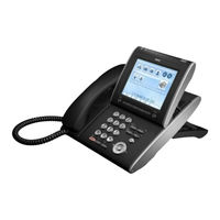
NEC NEAX 2400 IPX User Manual (228 pages)
Brand:
NEC
| Category:
Telephone
| Size: 8.22 MB
Table of Contents
Table of Contents
3
1 Introduction
7
Face Layout
7
Technical Specifications
8
Keys and Parts
9
PHONE START up and MENU SCREEN (Firmware Version 4.0.0.0 and Later)
12
Menu Screen
14
PHONE START up and MENU SCREEN (Firmware Version before 4.0.0.0)
16
Firmware Version before
16
Shortcut Menu
20
Desi-Less Screen
21
Soft Keys
25
MULTI-WINDOW (Firmware Version 4.0.0.0 and Later)
29
POP-UP WINDOWS (Firmware Version 4.0.0.0 and Later)
34
POP-UP WINDOWS (Firmware Version 3.0.0.0)
37
2 Terminal Setup
39
Setup with Up/Down Key
39
Setup with Feature Key
40
Setup with Menu Key
41
Incoming Call
43
Change Password
72
Back Light
72
Popup Window
83
3 Basic Operation
105
To Login
106
To Logout
106
To Make an External Call
107
To Make an Internal Call
108
To Answer an External Call
110
To Answer an Internal Call
111
Multiline Appearance
112
To Hold a Call
113
To Place a Call on Exclusive Hold
114
To Transfer a Call
115
To Originate a Call Using Selective Dialing (Dynamic Dial Pad, Preset Dial)
116
Dynamic Dial Pad
116
One-Touch Speed Calling Keys
117
Speed Calling - Station/Group
123
Speed Calling - System
124
Last Number Redial
124
Voice Call
125
Three-Party Conference
125
Voice Mail System
126
Do Not Disturb
126
How to Input Characters
127
Security Mode
141
Emergency Call
143
Phonebook
144
Local Phonebook
147
To Edit an Entry
150
Call History
155
To Delete Specific Data
156
4 Directory Operation
159
To Add New Data
159
Group Setting
160
To Change Group Name
167
To Find a Registered Data
168
To Search by Name
171
To Make a Call from Directory
185
To Add Prefix to Number
187
To Edit Directory Data
191
To Delete All Data
192
To Delete Specific Data
193
5 Call History Operation
197
To View Call History
198
To Make a Call from Call History
199
To Add Call History Data to Directory
201
To Edit Directory Data from Call History
204
To Delete All Data
208
To Delete Specific Data
209
6 Menu List
211
Menu List for Dt750
211
7 Web Programming
221
To Login
222
To Logout
224
How to Operate
226
Advertisement
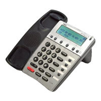
NEC NEAX 2400 IPX User Manual (89 pages)
Internet Protocol Exchange
Brand:
NEC
| Category:
IP Phone
| Size: 1.17 MB
Table of Contents
Table of Contents
5
Face Layout
7
Product View
11
Rear View
21
Base View
24
Keys and Lamps
25
Soft Keys
27
Terminal Setup with the Up/Down Key
34
Terminal Setup with the Feature Key
36
Login/Logout (IP Enabled D Term Term IP Only)
40
To Originate an Outside Call
42
To Originate an Internal Call
42
Multiline Appearance
42
To Originate a Call Using Speed Calling (One-Touch Speed Calling Keys)
43
LCD Indication of Dterm16Ld, Dterm16Ldip and 16LD ADM
44
To Register Name on One-Touch Speed Calling Key
45
To Originate a Call Using Speed Calling (-Station/Group)
46
To Originate a Call Using Speed Calling - System
46
To Originate a Call Using Telephone Directory (16LD ADM)
47
To Originate a Call Using Calling History
49
Account Code
50
Forced Account Code
50
Authorization Code
51
Voice Call
51
To Answer a Voice Call Hands Free
52
Automatic Intercom
53
Manual Intercom
54
Dial Intercom
55
To Place a Call on Hold
56
To Place a Call on Exclusive Hold
56
To Transfer a Call
57
Conference
58
To Establish a Broker Call
58
To Answer a Camped-On Call
59
Call Waiting - Originating
59
Call Park
61
Call Pick-Up (Group)
62
Call Pick-Up (Direct)
62
Outgoing Trunk Queuing
63
Off-Hook Trunk Queuing
63
Executive Override
64
Last Number Redial
64
Call Forwarding - All Calls
65
Call Forwarding - Busy Line
66
Call Forwarding - Don't Answer
68
Logged out IP Station - Call Destination
69
Call Back
71
To Save and Repeat a Number
72
To Leave a Message
73
To Answer a Message
73
Voice Mail System
74
Meet-Me Paging
75
Paging Transfer
76
Boss/Secretary Transfer
77
Boss/Secretary - MW Lamp Control
78
Boss/Secretary Override
79
Do Not Disturb
80
Call Redirect
81
Privacy
83
Privacy Release
84
LCD Indication
85
Index
89
NEC NEAX 2400 IPX User Manual (80 pages)
NEC telephone USER GUIDE
Brand:
NEC
| Category:
Telephone
| Size: 1.36 MB
Table of Contents
Table of Contents
3
Face Layout
5
Rear View
16
Base View
19
Keys and Lamps
20
Soft Keys
22
Terminal Setup with the Up/Down Key
29
Terminal Setup with the Feature Key
31
Login/Logout (IP Enabled D Term Term IP Only)
35
To Originate an Outside Call
37
To Originate an Internal Call
37
Multiline Appearance
37
To Originate a Call Using Speed Calling (One-Touch Buttons)
38
To Originate a Call Using Speed Calling (Individual/Group)
39
To Originate a Call Using Speed Calling - System
39
Account Code
40
Forced Account Code
40
Authorization Code
41
Voice Call
41
To Answer a Voice Call Hands Free
42
Automatic Intercom
43
Manual Intercom
44
Dial Intercom
45
To Place a Call on Hold
46
To Place a Call on Exclusive Hold
46
To Transfer a Call
47
Conference
48
To Establish a Broker Call
48
To Answer a Camped-On Call
49
Call Waiting - Originating
49
Call Park
51
Call Pick-Up (Group)
52
Call Pick-Up (Direct)
52
Outgoing Trunk Queuing
53
Off-Hook Trunk Queuing
53
Executive Override
54
Last Number Redial
54
Call Forwarding - All Calls
55
Call Forwarding - Busy Line
56
Call Forwarding - Don't Answer
58
Logged out IP Station - Call Destination
59
Call Back
61
To Save and Repeat a Number
62
To Leave a Message
63
To Answer a Message
63
Voice Mail System
64
Meet-Me Paging
65
Paging Transfer
66
Boss/Secretary Transfer
67
Boss/Secretary - MW Lamp Control
68
Boss/Secretary Override
69
Do Not Disturb
70
Call Redirect
71
Privacy
73
Privacy Release
74
Index
75
LCD Indication
77
NEC NEAX 2400 IPX User Manual (58 pages)
Internet protocol eXchange
Brand:
NEC
| Category:
Telephone
| Size: 0.35 MB
Table of Contents
Table of Contents
4
Introduction
6
Loop Key
7
Keys and Lamps
8
Incoming Call Identification
14
To Answer an Incoming Call
18
To Transfer an Incoming Call
19
Interposition Transfer
21
Console to Console Calling
22
To Answer Console Recall
23
To Originate a Call
26
To Hold a Call
27
To Record a Call
28
To Originate an Outside Call for a Station
29
Call Splitting (Three-Way Conference)
31
Console Initiated Three-Way Conference
32
Individual Trunk Access
33
Console Override
34
Call Forwarding (All Calls, Busy, no Answer)
35
Call Park
36
Overhead Paging
37
Meet-Me Paging Attendant
38
Serial Call
40
Message Waiting from Console
41
Position Busy (for Lunch, Breaks, Etc.)
42
Night Connection
43
(For Activation of Night Features at Close of Business Day)
43
Configuration Menu
44
Lamp Check Procedure
56
Notes
57
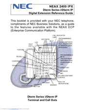
NEC NEAX 2400 IPX Reference Manual (20 pages)
Dterm Series i/Dterm IP Digital Extension
Brand:
NEC
| Category:
Telephone Accessories
| Size: 2.34 MB
Advertisement
Related Products
NEC NEAX 2000IVS Dterm E Series
NEC NEAX 2400 ICS
NEC NEAX2400IPX
NEC NEAX7400 ICS M120e
NEC NEAX 1400 IMS
NEC NEAX1400 IMS
NEC NDK 900
NEC NVM-CA Series
NEC NVM-202exCA
NEC NVM-2000CA
NEC Categories
Monitor
Projector
Server
Telephone
Computer Hardware
More NEC Manuals
Login
Sign In
OR
Sign in with Facebook
Sign in with Google
Upload manual
Upload from disk
Upload from URL