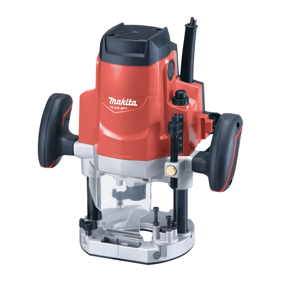
Makita M3600 Instruction Manual
Hide thumbs
Also See for M3600:
- Instruction manual (81 pages) ,
- Instruction manual (68 pages) ,
- Instruction manual (33 pages)
Advertisement
Table of Contents
Advertisement
Table of Contents

Summary of Contents for Makita M3600
- Page 1 INSTRUCTION MANUAL Router M3600 DOUBLE INSULATION Read before use.
-
Page 2: Specifications
Switching operations of electric apparatus cause volt- For European countries only age fluctuations. The operation of this device under Makita declares that the following Machine(s): unfavorable mains conditions can have adverse effects Designation of Machine: Router to the operation of other equipment. With a mains Model No./ Type: M3600... - Page 3 The technical file in accordance with 2006/42/EC is Personal Safety available from: Stay alert, watch what you are doing and use Makita, Jan-Baptist Vinkstraat 2, 3070, Belgium common sense when operating a power tool. 4.8.2015 Do not use a power tool while you are tired or under the influence of drugs, alcohol or med- ication.
-
Page 4: Functional Description
Service SAVE THESE INSTRUCTIONS. Have your power tool serviced by a qualified repair person using only identical replacement WARNING: DO NOT let comfort or familiarity with parts. This will ensure that the safety of the power product (gained from repeated use) replace strict adher- tool is maintained. - Page 5 Fig.2 Fig.4 ► 1. Knob ► 1. Switch lever Hold the tool firmly when turning CAUTION: CAUTION: Since excessive cutting may cause overload of the motor or difficulty in controlling off the tool, to overcome the reaction. the tool, the depth of cut should not be more than 20 mm (13/16″) at a pass when cutting grooves.
-
Page 6: Operation
NOTE: Moving the tool forward too fast may cause OPERATION a poor quality of cut, or damage to the router bit or motor. Moving the tool forward too slowly may burn and mar the cut. The proper feed rate will depend on CAUTION: Before operation, always make the router bit size, the kind of workpiece and depth... - Page 7 Straight guide (Type B) Optional accessory Insert the straight guide into the holes in the tool base and tighten the thumb screw. To adjust the distance between the router bit and the straight guide, loosen the thumb screw. At the desired distance, tighten the thumb screw to secure the straight guide in place.
- Page 8 Trimmer guide (Type A) Optional accessory Install the trimmer guide on the guide holder with the thumb screw (B). Insert the guide holder into the holes in the tool base and tighten the thumb screw (A). To adjust the distance between the router bit and the trimmer guide, loosen the thumb screw (B) and turn the fine adjusting screw.
-
Page 9: Maintenance
Removing the vacuum head Dust extraction Raise the lock lever. Optional accessory Pull the vacuum head out of the tool base while Use the vacuum head for dust extraction. holding the supports between thumb and finger. MAINTENANCE CAUTION: Always be sure that the tool is switched off and unplugged before attempting to perform inspection or maintenance. -
Page 10: Optional Accessories
Unit:mm spring. To maintain product SAFETY and RELIABILITY, repairs, any other maintenance or adjustment should be performed by Makita Authorized or Factory Service 1/4″ Centers, always using Makita replacement parts. 1/2″ 1/2″... - Page 11 Drill point flush trimming bit “V”Grooving bit Fig.28 Fig.30 Unit:mm Unit:mm θ 1/4″ 90° Dovetail bit Drill point double flush trimming bit Fig.29 Unit:mm Fig.31 θ Unit:mm 14.5 35° 3/8″ 14.5 14.5 23° 3/8″ 30° 3/8″ 11 ENGLISH...
- Page 12 Slotting cutter Corner rounding bit Fig.32 Fig.34 Unit:mm Unit:mm 1/2″ Chamfering bit 1/2″ Board-jointing bit Fig.35 Unit:mm 1/2″ Fig.33 Unit:mm 12 ENGLISH...
- Page 13 Cove beading bit Fig.36 Fig.38 Unit:mm θ Unit:mm 30° 45° 60° Beading bit Ball bearing flush trimming bit Fig.37 Fig.39 Unit:mm Unit:mm 1/2″ 1/4″ 13 ENGLISH...
- Page 14 Ball bearing corner rounding bit Ball bearing beading bit Fig.40 Fig.42 Unit:mm Unit:mm 1/4″ Ball bearing cove beading bit Ball bearing chamfering bit Fig.43 Fig.41 Unit:mm Unit:mm θ 45° 1/4″ 60° 14 ENGLISH...
- Page 15 Ball bearing roman ogee bit Fig.44 Unit:mm Double ball bearing round corner bit Fig.45 Unit:mm 1/2″...
- Page 16 Makita Jan-Baptist Vinkstraat 2, 3070, Belgium Makita Corporation Anjo, Aichi, Japan 885472-224 www.makita.com 20150928...


